Fluke 726 FE 726 Users Manual - Page 61
Pressure Switch Test, Testing an Output Device, KM
 |
View all Fluke 726 manuals
Add to My Manuals
Save this manual to your list of manuals |
Page 61 highlights
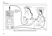
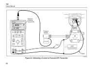
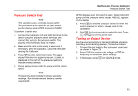
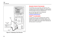
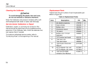
Pressure Switch Test Note This example uses a normally-closed switch. The procedure is the same for an open switch but the display reads OPEN instead of CLOSE. To perform a switch test: 1. Connect the Calibrator mA and COM terminals to the switch using the pressure switch terminals and connect the pump to the pressure switch. The polarity of the terminals does not matter. 2. Make sure the vent on the pump is open and, if necessary, zero the Calibrator. Close the vent after zeroing the Calibrator. 3. Press Q to enter switch-test mode. The upper display indicates the applied pressure. CLOSE is displayed to the right of the pressure reading to indicate closed contacts. 4. Slowly apply pressure with the pump until the switch opens. Note Pressure the device slowly to ensure accurate readings. Run the test several times to confirm repeatability. Multifunction Process Calibrator Pressure Switch Test OPEN displays once the switch is open. Slowly bleed the pump until the pressure switch closes. RECALL appears on the display. 5. Press Q to read the pressure values for when the switch opened, for when it closed, and for the deadband. 6. Hold Q for three seconds to restart the test. Press A OR U to exit the switch test. Testing an Output Device Use the source functions to test and calibrate actuators, recording, and indicating devices. Proceed as follows: 1. Connect the test leads to the instrument under test as shown in Figure 23. 2. Press V for current or dc voltage, or K for frequency or resistance (lower display). M 3. If necessary, press for SOURCE mode. 51
-
 1
1 -
2
-
3
-
4
-
5
-
6
-
7
-
8
-
9
-
10
-
11
-
12
-
13
-
14
-
15
-
16
-
17
-
18
-
19
-
20
-
21
-
22
-
23
-
24
-
25
-
26
-
27
-
28
-
29
-
30
-
31
-
32
-
33
-
34
-
35
-
36
-
37
-
38
-
39
-
40
-
41
-
42
-
43
-
44
-
45
-
46
-
47
-
48
-
49
-
50
-
51
-
52
-
53
-
54
-
55
-
 56
56 -
 57
57 -
 58
58 -
 59
59 -
 60
60 -
 61
61 -
 62
62 -
 63
63 -
 64
64 -
 65
65 -
 66
66 -
67
-
68
-
69
-
70
-
71
-
72
-
73
-
74
-
75
-
76
-
77
-
78
-
79
-
80
 |
 |
