Fluke 726 FE 726 Users Manual - Page 49
procedures depending on module type., module's Instruction Sheet. Modules vary in zeroing
 |
View all Fluke 726 manuals
Add to My Manuals
Save this manual to your list of manuals |
Page 49 highlights
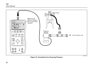
1. Connect a pressure module to the Calibrator as shown in Figure 18. The threads on the pressure modules accept standard ¼ NPT pipe fittings. Use the supplied ¼ NPT to ¼ ISO adapter if necessary. 2. Press U (lower display). The Calibrator automatically senses which pressure module is attached and sets its range accordingly. Multifunction Process Calibrator Using Source Mode 3. Zero the pressure module as described in the module's Instruction Sheet. Modules vary in zeroing procedures depending on module type. 4. Pressurize the pressure line with the pressure source to the desired level as shown on the display. If desired, continue pressing U to change pressure display units to psi, mmHg, inHg, cmH2O@4 °C, cmH O@20 2 °C, inH O@4 2 °C, inH2O@20 °C, inH2O@60 °C, mbar, bar, kg/cm2, or kPa. 39
-
 1
1 -
2
-
3
-
4
-
5
-
6
-
7
-
8
-
9
-
10
-
11
-
12
-
13
-
14
-
15
-
16
-
17
-
18
-
19
-
20
-
21
-
22
-
23
-
24
-
25
-
26
-
27
-
28
-
29
-
30
-
31
-
32
-
33
-
34
-
35
-
36
-
37
-
38
-
39
-
40
-
41
-
42
-
43
-
 44
44 -
 45
45 -
 46
46 -
 47
47 -
 48
48 -
 49
49 -
 50
50 -
 51
51 -
 52
52 -
 53
53 -
 54
54 -
55
-
56
-
57
-
58
-
59
-
60
-
61
-
62
-
63
-
64
-
65
-
66
-
67
-
68
-
69
-
70
-
71
-
72
-
73
-
74
-
75
-
76
-
77
-
78
-
79
-
80
 |
 |
