Fluke 726 FE 726 Users Manual - Page 23
Display, for Calibrator Setups
 |
View all Fluke 726 manuals
Add to My Manuals
Save this manual to your list of manuals |
Page 23 highlights
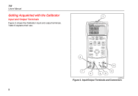
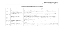
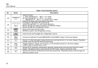
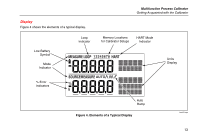
Display Figure 4 shows the elements of a typical display. Low Battery Symbol Mode Indicator Loop Indicator Multifunction Process Calibrator Getting Acquainted with the Calibrator Memory Locations for Calibrator Setups HART Mode Indicator Units Display % Error Indicators Auto Ramp Figure 4. Elements of a Typical Display bec07f.eps 13
-
 1
1 -
2
-
3
-
4
-
5
-
6
-
7
-
8
-
9
-
10
-
11
-
12
-
13
-
14
-
15
-
16
-
17
-
 18
18 -
 19
19 -
 20
20 -
 21
21 -
 22
22 -
 23
23 -
 24
24 -
 25
25 -
 26
26 -
 27
27 -
 28
28 -
29
-
30
-
31
-
32
-
33
-
34
-
35
-
36
-
37
-
38
-
39
-
40
-
41
-
42
-
43
-
44
-
45
-
46
-
47
-
48
-
49
-
50
-
51
-
52
-
53
-
54
-
55
-
56
-
57
-
58
-
59
-
60
-
61
-
62
-
63
-
64
-
65
-
66
-
67
-
68
-
69
-
70
-
71
-
72
-
73
-
74
-
75
-
76
-
77
-
78
-
79
-
80
 |
 |

Multifunction Process Calibrator
Getting Acquainted with the Calibrator
13
Display
Figure 4 shows the elements of a typical display.
Low Battery
Symbol
Loop
Indicator
Memory Locations
for Calibrator Setups
Units
Display
Auto
Ramp
Mode
Indicator
HART Mode
Indicator
% Error
Indicators
bec07f.eps
Figure 4. Elements of a Typical Display