Gateway NV-42 Service Guide - Page 65
Main Unit Disassembly Process
 |
View all Gateway NV-42 manuals
Add to My Manuals
Save this manual to your list of manuals |
Page 65 highlights
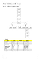
Main Unit Disassembly Process Main Unit Disassembly Flowchart Remove External Modules before proceeding Rem ove Switch Cover Rem ove Keyboard Rem ove LCD Module Upper Cover Rem ove Upper Cover Lower Cover Rem ove TouchPad FFC Rem ove Speaker Module Rem ove RTC Battery Rem ove Modem Module Rem ove USB Board Rem ove Bluetooth Rem ove Mainboard Rem ove Thermal Module Screw List Step Switch Cover LCD Module Upper Cover Speaker Modules Modem Board USB Board Mainboard Screw M2.5*6.0 M2.5*6.0 M2.5*6.0 M2.5*6.0 M2*3 M2*3 M2*3 M2.5*6.0 Rem ove CPU Quantity 3 4 8 10 4 2 1 1 Part No. 86.W0907.002 86.W0907.002 86.W0907.002 86.W0907.002 86.A08V7.005 86.A08V7.005 86.A08V7.005 86.W0907.002 Chapter 3 55
-
 1
1 -
2
-
3
-
4
-
5
-
6
-
7
-
8
-
9
-
10
-
11
-
12
-
13
-
14
-
15
-
16
-
17
-
18
-
19
-
20
-
21
-
22
-
23
-
24
-
25
-
26
-
27
-
28
-
29
-
30
-
31
-
32
-
33
-
34
-
35
-
36
-
37
-
38
-
39
-
40
-
41
-
42
-
43
-
44
-
45
-
46
-
47
-
48
-
49
-
50
-
51
-
52
-
53
-
54
-
55
-
56
-
57
-
58
-
59
-
 60
60 -
 61
61 -
 62
62 -
 63
63 -
 64
64 -
 65
65 -
 66
66 -
 67
67 -
 68
68 -
 69
69 -
 70
70 -
71
-
72
-
73
-
74
-
75
-
76
-
77
-
78
-
79
-
80
-
81
-
82
-
83
-
84
-
85
-
86
-
87
-
88
-
89
-
90
-
91
-
92
-
93
-
94
-
95
-
96
-
97
-
98
-
99
-
100
-
101
-
102
-
103
-
104
-
105
-
106
-
107
-
108
-
109
-
110
-
111
-
112
-
113
-
114
-
115
-
116
-
117
-
118
-
119
-
120
-
121
-
122
-
123
-
124
-
125
-
126
-
127
-
128
-
129
-
130
-
131
-
132
-
133
-
134
-
135
-
136
-
137
-
138
-
139
-
140
-
141
-
142
-
143
-
144
-
145
-
146
-
147
-
148
-
149
-
150
-
151
-
152
-
153
-
154
-
155
-
156
-
157
-
158
-
159
-
160
-
161
-
162
-
163
-
164
-
165
-
166
-
167
-
168
-
169
-
170
-
171
-
172
-
173
-
174
-
175
-
176
-
177
-
178
-
179
-
180
-
181
-
182
-
183
-
184
-
185
-
186
-
187
-
188
-
189
-
190
-
191
-
192
-
193
-
194
-
195
-
196
-
197
-
198
-
199
-
200
 |
 |

Chapter 3
55
Main Unit Disassembly Process
Main Unit Disassembly Flowchart
Screw List
Step
Screw
Quantity
Part No.
Switch Cover
M2.5*6.0
3
86.W0907.002
LCD Module
M2.5*6.0
4
86.W0907.002
Upper Cover
M2.5*6.0
8
86.W0907.002
M2.5*6.0
10
86.W0907.002
Speaker Modules
M2*3
4
86.A08V7.005
Modem Board
M2*3
2
86.A08V7.005
USB Board
M2*3
1
86.A08V7.005
Mainboard
M2.5*6.0
1
86.W0907.002
Re
m
ove
Mainboard
Re
m
ove
USB Board
Re
m
ove
Switch Cover
Re
m
ove
Keyboard
Re
m
ove
Upper Cover
Re
m
ove
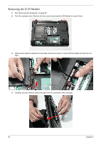
LCD Module
Re
m
ove Extern
a
l
Modules be
f
ore
proceeding
Re
m
ove
TouchPad FFC
Upper
Cover
Lower
Cover
Re
m
ove
Speaker Module
Re
m
ove
Modem Module
Re
m
ove
CPU
Re
m
ove
RTC Battery
Re
m
ove
Thermal Module
Re
m
ove
Bluetooth