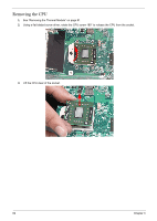
Gateway NV-42 Service Guide - Page 93
LCD Module Disassembly Process
 |
View all Gateway NV-42 manuals
Add to My Manuals
Save this manual to your list of manuals |
Page 93 highlights
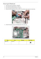
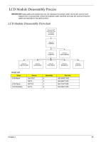
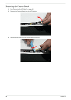
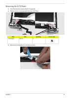
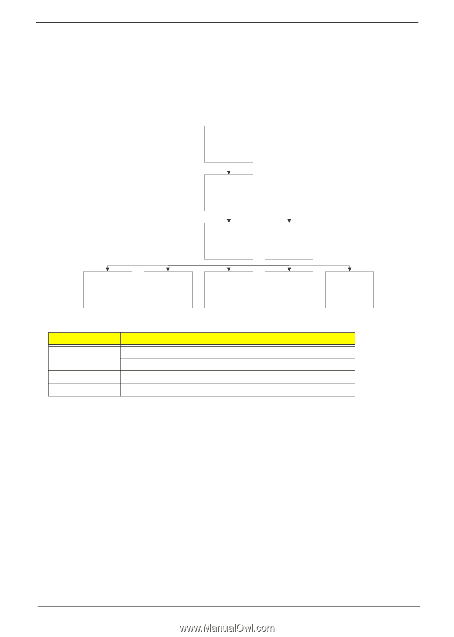
LCD Module Disassembly Process IMPORTANT:Cable paths and positioning may not represent the actual model. During the removal and replacement of components, ensure all available cable channels and clips are used and that the cables are replaced in the same position. LCD Module Disassembly Flowchart Remove LCD Panel from Main Unit before proceeding Rem ove LCD Bezel Rem ove LCD Panel Rem ove Camera Module Rem ove LCD FPC Cable Rem ove LCD Brackets Rem ove Power Board Rem ove Microphone Rem ove Antennas Screw List Step LCD Bezel LCD Panel LCD Brackets Screw M2.5*6.0 M2*3 M2*3.5 M2*3 Quantity 6 2 4 4 Part No. 86.W0907.002 86.A08V7.005 86.T23V7.005 86.A08V7.005 Chapter 3 83
-
 1
1 -
2
-
3
-
4
-
5
-
6
-
7
-
8
-
9
-
10
-
11
-
12
-
13
-
14
-
15
-
16
-
17
-
18
-
19
-
20
-
21
-
22
-
23
-
24
-
25
-
26
-
27
-
28
-
29
-
30
-
31
-
32
-
33
-
34
-
35
-
36
-
37
-
38
-
39
-
40
-
41
-
42
-
43
-
44
-
45
-
46
-
47
-
48
-
49
-
50
-
51
-
52
-
53
-
54
-
55
-
56
-
57
-
58
-
59
-
60
-
61
-
62
-
63
-
64
-
65
-
66
-
67
-
68
-
69
-
70
-
71
-
72
-
73
-
74
-
75
-
76
-
77
-
78
-
79
-
80
-
81
-
82
-
83
-
84
-
85
-
86
-
87
-
 88
88 -
 89
89 -
 90
90 -
 91
91 -
 92
92 -
 93
93 -
 94
94 -
 95
95 -
 96
96 -
 97
97 -
 98
98 -
99
-
100
-
101
-
102
-
103
-
104
-
105
-
106
-
107
-
108
-
109
-
110
-
111
-
112
-
113
-
114
-
115
-
116
-
117
-
118
-
119
-
120
-
121
-
122
-
123
-
124
-
125
-
126
-
127
-
128
-
129
-
130
-
131
-
132
-
133
-
134
-
135
-
136
-
137
-
138
-
139
-
140
-
141
-
142
-
143
-
144
-
145
-
146
-
147
-
148
-
149
-
150
-
151
-
152
-
153
-
154
-
155
-
156
-
157
-
158
-
159
-
160
-
161
-
162
-
163
-
164
-
165
-
166
-
167
-
168
-
169
-
170
-
171
-
172
-
173
-
174
-
175
-
176
-
177
-
178
-
179
-
180
-
181
-
182
-
183
-
184
-
185
-
186
-
187
-
188
-
189
-
190
-
191
-
192
-
193
-
194
-
195
-
196
-
197
-
198
-
199
-
200
 |
 |
Chapter 3
83
LCD Module Disassembly Process
IMPORTANT:
Cable paths and positioning may not represent the actual model. During the removal and
replacement of components, ensure all available cable channels and clips are used and that the
cables are replaced in the same position.
LCD Module Disassembly Flowchart
Screw List
Step
Screw
Quantity
Part No.
LCD Bezel
M2.5*6.0
6
86.W0907.002
M2*3
2
86.A08V7.005
LCD Panel
M2*3.5
4
86.T23V7.005
LCD Brackets
M2*3
4
86.A08V7.005
Re
m
ove
LCD Panel
Re
m
ove
LCD Bezel
Re
m
ove
LCD FPC Cable
Re
m
ove LCD
P
a
nel
f
ro
m
M
a
in
Unit be
f
ore
proceeding
Re
m
ove
LCD Brackets
Re
m
ove
Antennas
Re
m
ove
Camera Module
Re
m
ove
Microphone
Re
m
ove
Power Board