HP 11kVA 400 Volt IEC309 16A 3-Phase Input 30xC13/3xC19 HP Monitored Power Dis - Page 49
Display Submenu, Daisy Chain Submenu, Example Settings Menu Display
 |
View all HP 11kVA 400 Volt IEC309 16A 3-Phase Input 30xC13/3xC19 manuals
Add to My Manuals
Save this manual to your list of manuals |
Page 49 highlights
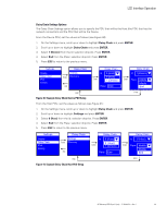
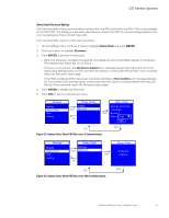
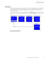
LCD Interface Operation On the Main Menu, scroll up or down to highlight Settings. Press ENTER. Scroll up or down to select a submenu and press ENTER to display the submenu options. Press ESC to return to the previous menu. Main Menu Active Alarms Alarms History Meter SSeettttiinnggss PDU Info Enter Settings LDCisDplay Daisy Chain IPv4 Factory ESC Figure 38. Example Settings Menu Display Display Submenu The Display submenu allows you to customize settings for LCD contrast and orientation (see Figure 39). On the Settings menu, scroll up or down to highlight DISPLAY. Press ENTER to display the screens to set the values for the submenu. After you select the values, press ENTER to set the values as displayed on the screen. Press ESC to return to the previous menu. Settings Display Daisy Chain IPv4 Factory LCD LCD Contrast: 0C°ontrast: 35 Enter 9305°° Enter 180° Orientation: O- r9ie0n°tation: 0 ° 0 ° ESC Enter Figure 39. Example Display Submenu Displays Daisy Chain Submenu The Daisy Chain submenu allows you to configure two PDUs to be monitored from a single Ethernet connection on the Host PDU. Use the two Daisy Chain submenu options (Settings and Discovery) to configure the PDUs. NOTE To configure and monitor the PDUs, they must be connected together through the Daisy Chain connector using an Ethernet cable. In addition, the Host PDU must be connected to the network. Use the Settings option for the first two configuration steps: 1. From the PDU designated as the Device PDU, access the Daisy Chain Settings option and set the Device values. 2. From the PDU designated as the Host PDU, access the Daisy Chain Settings option and set the Host values. Use the Discovery option for the final configuration step: 3. From the Host PDU, access the Daisy Chain Discovery option to start communication between the Host and the Device PDU. HP Monitored PDU User's Guide P-164000281-Rev 1 43
-
 1
1 -
2
-
3
-
4
-
5
-
6
-
7
-
8
-
9
-
10
-
11
-
12
-
13
-
14
-
15
-
16
-
17
-
18
-
19
-
20
-
21
-
22
-
23
-
24
-
25
-
26
-
27
-
28
-
29
-
30
-
31
-
32
-
33
-
34
-
35
-
36
-
37
-
38
-
39
-
40
-
41
-
42
-
43
-
 44
44 -
 45
45 -
 46
46 -
 47
47 -
 48
48 -
 49
49 -
 50
50 -
 51
51 -
 52
52 -
 53
53 -
 54
54 -
55
-
56
-
57
-
58
-
59
-
60
-
61
-
62
-
63
-
64
-
65
-
66
-
67
-
68
-
69
-
70
-
71
-
72
-
73
-
74
-
75
-
76
-
77
-
78
-
79
-
80
-
81
-
82
-
83
-
84
-
85
-
86
-
87
-
88
-
89
-
90
-
91
-
92
-
93
-
94
-
95
-
96
-
97
-
98
-
99
-
100
-
101
-
102
-
103
-
104
-
105
-
106
-
107
-
108
-
109
-
110
-
111
-
112
-
113
-
114
-
115
-
116
-
117
-
118
-
119
-
120
 |
 |
