HP Brocade 8/12c Fabric OS Encryption Administrator's Guide - Page 208
Virtual host port 2, through the shared host port, to target port 2
 |
View all HP Brocade 8/12c manuals
Add to My Manuals
Save this manual to your list of manuals |
Page 208 highlights
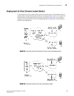
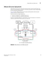
4 VMware ESX server deployments Figure 107 shows a VMware ESX server with two guest operating systems where two guests access a fabric over a shared port. To enable this, both guests are assigned a virtual port. There are two paths to a target storage device: • Virtual host port 1, through the shared host port, to target port 1, redirected through CTC T1. • Virtual host port 2, through the shared host port, to target port 2, redirected through CTC T2. In this case, the virtual host port 1 is zoned with target port 1, and the virtual host port 2 is zoned with target port 2 to enable the redirection zoning needed to redirect traffic to the correct CTC. Key Management Appliance or Key Vault Management Network LAN DCFM CTC1 (T1) Management Link Management Link VMware ESX Server Guest OS1 Guest OS2 V-Port1 V-Port2 FC HBA Host Port1 (I1) Fabric 1 CTC2 (T2) BES1 Target Port1 (T1) Target Port2 (T2) BES4 EncrDypEtKioCnlGusroteurp Target Io Sync Link Dedicated Cluster Network LAN IO Sync Link CTC1 - CTC for Target Port T1 hosted on BES1 in DEK Cluster CTC2 - CTC for Target Port T2 hosted on BES2 in DEK Cluster FIGURE 107 VMware ESX server, One HBA shared by two guest OS 188 Fabric OS Encryption Administrator's Guide 53-1002159-03
-
 1
1 -
2
-
3
-
4
-
5
-
6
-
7
-
8
-
9
-
10
-
11
-
12
-
13
-
14
-
15
-
16
-
17
-
18
-
19
-
20
-
21
-
22
-
23
-
24
-
25
-
26
-
27
-
28
-
29
-
30
-
31
-
32
-
33
-
34
-
35
-
36
-
37
-
38
-
39
-
40
-
41
-
42
-
43
-
44
-
45
-
46
-
47
-
48
-
49
-
50
-
51
-
52
-
53
-
54
-
55
-
56
-
57
-
58
-
59
-
60
-
61
-
62
-
63
-
64
-
65
-
66
-
67
-
68
-
69
-
70
-
71
-
72
-
73
-
74
-
75
-
76
-
77
-
78
-
79
-
80
-
81
-
82
-
83
-
84
-
85
-
86
-
87
-
88
-
89
-
90
-
91
-
92
-
93
-
94
-
95
-
96
-
97
-
98
-
99
-
100
-
101
-
102
-
103
-
104
-
105
-
106
-
107
-
108
-
109
-
110
-
111
-
112
-
113
-
114
-
115
-
116
-
117
-
118
-
119
-
120
-
121
-
122
-
123
-
124
-
125
-
126
-
127
-
128
-
129
-
130
-
131
-
132
-
133
-
134
-
135
-
136
-
137
-
138
-
139
-
140
-
141
-
142
-
143
-
144
-
145
-
146
-
147
-
148
-
149
-
150
-
151
-
152
-
153
-
154
-
155
-
156
-
157
-
158
-
159
-
160
-
161
-
162
-
163
-
164
-
165
-
166
-
167
-
168
-
169
-
170
-
171
-
172
-
173
-
174
-
175
-
176
-
177
-
178
-
179
-
180
-
181
-
182
-
183
-
184
-
185
-
186
-
187
-
188
-
189
-
190
-
191
-
192
-
193
-
194
-
195
-
196
-
197
-
198
-
199
-
200
-
201
-
202
-
 203
203 -
 204
204 -
 205
205 -
 206
206 -
 207
207 -
 208
208 -
 209
209 -
 210
210 -
 211
211 -
 212
212 -
 213
213 -
214
-
215
-
216
-
217
-
218
-
219
-
220
-
221
-
222
-
223
-
224
-
225
-
226
-
227
-
228
-
229
-
230
-
231
-
232
-
233
-
234
-
235
-
236
-
237
-
238
-
239
-
240
-
241
-
242
-
243
-
244
-
245
-
246
-
247
-
248
-
249
-
250
-
251
-
252
-
253
-
254
-
255
-
256
-
257
-
258
-
259
-
260
-
261
-
262
-
263
-
264
-
265
-
266
-
267
-
268
-
269
-
270
-
271
-
272
-
273
-
274
-
275
-
276
-
277
-
278
-
279
-
280
-
281
-
282
 |
 |
