HP Color 9850mfp Service Manual - Page 20
prevention circuit, Fixing upper lamp 1 L2, Fixing lower lamp L4 overheating - driver
 |
View all HP Color 9850mfp manuals
Add to My Manuals
Save this manual to your list of manuals |
Page 20 highlights
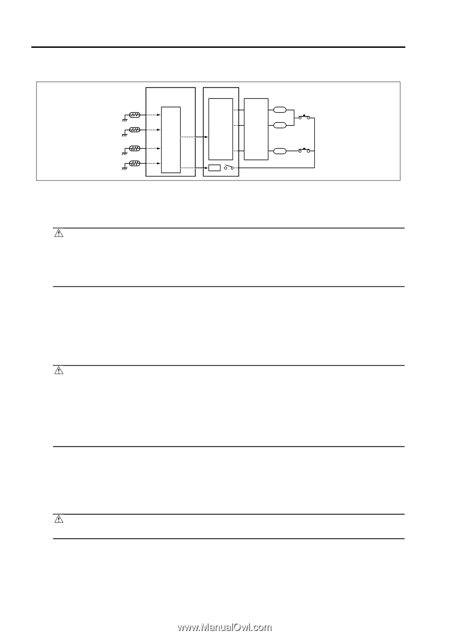
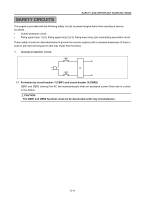
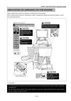
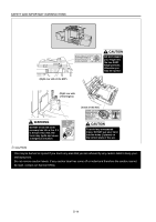
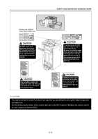
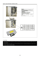
SAFETY AND IMPORTANT WARNING ITEMS 2. Fixing upper lamp 1 (L2), Fixing upper lamp 2 (L3), Fixing lower lamp (L4) overheating prevention circuit PRCB TH1 TH3 Control TH2 section TH4 ACDB AC driver section L2 TS1 L3 FHCB TS2 L4 RL1 RL1 2.1 Protection by software The output voltage from fixing temperature sensor 1 (TH1) and fixing temperature sensor 2 (TH2) is read by theCPU. If this voltage is abnormal, L2, L3, and L4 are turned OFF by opening main relay (RL1). CAUTION: • The clearance between the fixing upper roller and TH1 and the clearance between the fixing lower roller and TH2 must not be changed. When replacing them, make sure to comply with the specified clearances. • The RL1 function must not be deactivated under any circumstances. 2.2 Protection by the hardware circuit The output voltages from fixing temperature sensor 1 (TH1), fixing temperature sensor 2 (TH2), fixing temperaturesensor 3 (TH3), and fixing temperature sensor 4 (TH4) are compared with the abnormality judgment referencevalue in the comparator circuit. If the output voltage from TH1, TH2, TH3, or TH4 exceeds the reference value, L2,L3, and L4 are turned OFF by opening RL1. CAUTION: • The clearance between the fixing upper roller and TH1 and the clearance between the fixing lower roller and TH2 must not be changed. When replacing them, make sure to comply with the specified clearances. • Periodically check the contact between the fixing upper roller and TH3 and the contact between the fixing lower roller and TH4, and replace them if any abnormality is detected. • The RL1 function must not be deactivated under any circumstances. 2.3 Protection by thermostat 1 (TS1) and thermostat 2 (TS2) When the temperature of the fixing upper roller exceeds the specified value, TS1 is turned OFF, thus interrupting thepower to L2 and L3 directly. When the temperature of the fixing lower roller exceeds the specified value, TS2 isturned OFF, thus interrupting the power to L4 directly. CAUTION: Do not use any other electrical conductor in place of TS1 and TS2. S-12
-
 1
1 -
2
-
3
-
4
-
5
-
6
-
7
-
8
-
9
-
10
-
11
-
12
-
13
-
14
-
 15
15 -
 16
16 -
 17
17 -
 18
18 -
 19
19 -
 20
20 -
 21
21 -
 22
22 -
 23
23 -
 24
24 -
 25
25 -
26
-
27
-
28
-
29
-
30
-
31
-
32
-
33
-
34
-
35
-
36
-
37
-
38
-
39
-
40
-
41
-
42
-
43
-
44
-
45
-
46
-
47
-
48
-
49
-
50
-
51
-
52
-
53
-
54
-
55
-
56
-
57
-
58
-
59
-
60
-
61
-
62
-
63
-
64
-
65
-
66
-
67
-
68
-
69
-
70
-
71
-
72
-
73
-
74
-
75
-
76
-
77
-
78
-
79
-
80
-
81
-
82
-
83
-
84
-
85
-
86
-
87
-
88
-
89
-
90
-
91
-
92
-
93
-
94
-
95
-
96
-
97
-
98
-
99
-
100
-
101
-
102
-
103
-
104
-
105
-
106
-
107
-
108
-
109
-
110
-
111
-
112
-
113
-
114
-
115
-
116
-
117
-
118
-
119
-
120
-
121
-
122
-
123
-
124
-
125
-
126
-
127
-
128
-
129
-
130
-
131
-
132
-
133
-
134
-
135
-
136
-
137
-
138
-
139
-
140
-
141
-
142
-
143
-
144
-
145
-
146
-
147
-
148
-
149
-
150
-
151
-
152
-
153
-
154
-
155
-
156
-
157
-
158
-
159
-
160
-
161
-
162
-
163
-
164
-
165
-
166
-
167
-
168
-
169
-
170
-
171
-
172
-
173
-
174
-
175
-
176
-
177
-
178
-
179
-
180
-
181
-
182
-
183
-
184
-
185
-
186
-
187
-
188
-
189
-
190
-
191
-
192
-
193
-
194
-
195
-
196
-
197
-
198
-
199
-
200
-
201
-
202
-
203
-
204
-
205
-
206
-
207
-
208
-
209
-
210
-
211
-
212
-
213
-
214
-
215
-
216
-
217
-
218
-
219
-
220
-
221
-
222
-
223
-
224
-
225
-
226
-
227
-
228
-
229
-
230
-
231
-
232
-
233
-
234
-
235
-
236
-
237
-
238
-
239
-
240
-
241
-
242
-
243
-
244
-
245
-
246
-
247
-
248
-
249
-
250
-
251
-
252
-
253
-
254
-
255
-
256
-
257
-
258
-
259
-
260
-
261
-
262
-
263
-
264
-
265
-
266
-
267
-
268
-
269
-
270
-
271
-
272
-
273
-
274
-
275
-
276
-
277
-
278
-
279
-
280
-
281
-
282
-
283
-
284
-
285
-
286
-
287
-
288
-
289
-
290
-
291
-
292
-
293
-
294
-
295
-
296
-
297
-
298
-
299
-
300
-
301
-
302
-
303
-
304
-
305
-
306
-
307
-
308
-
309
-
310
-
311
-
312
-
313
-
314
-
315
-
316
-
317
-
318
-
319
-
320
-
321
-
322
-
323
-
324
-
325
-
326
-
327
-
328
-
329
-
330
-
331
-
332
-
333
-
334
-
335
-
336
-
337
-
338
-
339
-
340
-
341
-
342
-
343
-
344
-
345
-
346
-
347
-
348
-
349
-
350
-
351
-
352
-
353
-
354
-
355
-
356
-
357
-
358
-
359
-
360
-
361
-
362
-
363
-
364
-
365
-
366
-
367
-
368
-
369
-
370
-
371
-
372
-
373
-
374
-
375
-
376
-
377
-
378
-
379
-
380
-
381
-
382
-
383
-
384
-
385
-
386
-
387
-
388
-
389
-
390
-
391
-
392
-
393
-
394
-
395
-
396
-
397
-
398
-
399
-
400
-
401
-
402
-
403
-
404
-
405
-
406
-
407
-
408
-
409
-
410
-
411
-
412
-
413
-
414
-
415
-
416
-
417
-
418
-
419
-
420
-
421
-
422
-
423
-
424
-
425
-
426
-
427
-
428
-
429
-
430
-
431
-
432
-
433
-
434
-
435
-
436
-
437
-
438
-
439
-
440
-
441
-
442
-
443
-
444
-
445
-
446
-
447
-
448
-
449
-
450
-
451
-
452
-
453
-
454
-
455
-
456
-
457
-
458
-
459
-
460
-
461
-
462
-
463
-
464
-
465
-
466
-
467
-
468
-
469
-
470
-
471
-
472
-
473
-
474
-
475
-
476
-
477
-
478
-
479
-
480
-
481
-
482
-
483
-
484
-
485
-
486
-
487
-
488
-
489
-
490
-
491
-
492
-
493
-
494
-
495
-
496
-
497
-
498
-
499
-
500
-
501
-
502
-
503
-
504
-
505
-
506
-
507
-
508
-
509
-
510
-
511
-
512
-
513
-
514
-
515
-
516
-
517
-
518
-
519
-
520
-
521
-
522
 |
 |