HP Color 9850mfp Service Manual - Page 515
Signals, Booklet ejection to stacker, Upright stack/stacker full state detection, Safety mechanism
 |
View all HP Color 9850mfp manuals
Add to My Manuals
Save this manual to your list of manuals |
Page 515 highlights
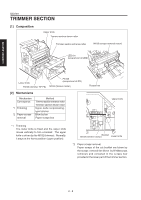
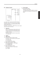
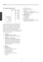
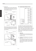
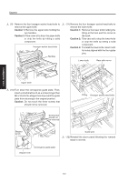
2 UNIT EXPLANATION Q3224A (2) Through mode When the PS101 (entrance) detects the leading edge (folding edge) of the conveyed booklet, the M107(pusher) turns ON to move the pusher plate to the turnout position to open the booklet ejection path. b. Booklet ejection to stacker (1) Trim mode When the specified time lapses after the PS108 (exit) detects the trailing edge (trim edge) of the booklet conveyed by the M101(conveyance), the M106(holder) starts reversing to lower the holder plate. When the PS111(lower limit) detects the lower limit of the holder plate, the M106 turns OFF. When the specified time lapses after the M106(holder) turns ON, the M107 turns ON again to drive the pusher plate to push out the booklet in the holder section to the exit tray. When the specified time lapses after the booklet is pushed out by the pusher plate, the M106 rotates in the forward direction to raise the holder plate. When the PS110(upper limit) detects the upper limit position of the holder plate, the M106 stops rotating in the forward direction, thus completing booklet ejection. (2) Through mode The operation in the through mode is the same as in the trim mode. c. Upright stack/stacker full state detection The booklet pushed out of the booklet ejection path is stacked upright between the pusher plate and the exit tray. When the total thickness of the stacked booklets becomes the specified value, the PS113(stacker full) turns ON to display the message indicating that the stacker is full on the operation panel of the engine. d. Safety mechanism If the stacker door is opened while this machine is operating, the MS3 and MS4 turn OFF to block the drive signal paths of the M106 and M107, causing this machine the to stop operating. At this time, PS114(stacker door) also turns OFF to display an error message on the operation panel of the engine. 2. Signals a. Input signals (1) PS110_SIG (PS110 to TUDB to finisher) Holder plate upper limit detection signal. [L]: Other than upper limit [H]: Upper limit (2) PS111_SIG (PS111 to TUDB to finisher) Holder plate lower limit detection signal. [L]: Other than lower limit [H]: Lower limit (3) PS112_SIG (PS112 to TUDB to finisher) Pusher plate home position detection signal. [L]: Home position [H]: Other than home position (4) IN (PS113 to TUDB) Stacker full state detection signal. [L]: Full [H]: Not full (5) M106_CONT (Finisher to TUDB) M106 ON/OFF control signal. [L]: M106 ON [H]: M106 OFF (6) M106_F/R (Finisher to TUDB) M106 rotational direction change signal. [L]: M106 Forward [H]: M106 Reverse (7) M107_CONT (Finisher to TUDB) M107 ON/OFF control signal. [L]: M107 ON [H]: M107 OFF b. Output signals (1) DRV (TUDB to M106) M106 drive control signal. The rotational direction of the M106 is controlled according to the combination of the levels of two DRVs. State Holder moves down Holder moves up Stop DRV H L L DRV L H L (2) DRV (TUDB to M107) M107 drive control signal. 2 - 13
-
 1
1 -
2
-
3
-
4
-
5
-
6
-
7
-
8
-
9
-
10
-
11
-
12
-
13
-
14
-
15
-
16
-
17
-
18
-
19
-
20
-
21
-
22
-
23
-
24
-
25
-
26
-
27
-
28
-
29
-
30
-
31
-
32
-
33
-
34
-
35
-
36
-
37
-
38
-
39
-
40
-
41
-
42
-
43
-
44
-
45
-
46
-
47
-
48
-
49
-
50
-
51
-
52
-
53
-
54
-
55
-
56
-
57
-
58
-
59
-
60
-
61
-
62
-
63
-
64
-
65
-
66
-
67
-
68
-
69
-
70
-
71
-
72
-
73
-
74
-
75
-
76
-
77
-
78
-
79
-
80
-
81
-
82
-
83
-
84
-
85
-
86
-
87
-
88
-
89
-
90
-
91
-
92
-
93
-
94
-
95
-
96
-
97
-
98
-
99
-
100
-
101
-
102
-
103
-
104
-
105
-
106
-
107
-
108
-
109
-
110
-
111
-
112
-
113
-
114
-
115
-
116
-
117
-
118
-
119
-
120
-
121
-
122
-
123
-
124
-
125
-
126
-
127
-
128
-
129
-
130
-
131
-
132
-
133
-
134
-
135
-
136
-
137
-
138
-
139
-
140
-
141
-
142
-
143
-
144
-
145
-
146
-
147
-
148
-
149
-
150
-
151
-
152
-
153
-
154
-
155
-
156
-
157
-
158
-
159
-
160
-
161
-
162
-
163
-
164
-
165
-
166
-
167
-
168
-
169
-
170
-
171
-
172
-
173
-
174
-
175
-
176
-
177
-
178
-
179
-
180
-
181
-
182
-
183
-
184
-
185
-
186
-
187
-
188
-
189
-
190
-
191
-
192
-
193
-
194
-
195
-
196
-
197
-
198
-
199
-
200
-
201
-
202
-
203
-
204
-
205
-
206
-
207
-
208
-
209
-
210
-
211
-
212
-
213
-
214
-
215
-
216
-
217
-
218
-
219
-
220
-
221
-
222
-
223
-
224
-
225
-
226
-
227
-
228
-
229
-
230
-
231
-
232
-
233
-
234
-
235
-
236
-
237
-
238
-
239
-
240
-
241
-
242
-
243
-
244
-
245
-
246
-
247
-
248
-
249
-
250
-
251
-
252
-
253
-
254
-
255
-
256
-
257
-
258
-
259
-
260
-
261
-
262
-
263
-
264
-
265
-
266
-
267
-
268
-
269
-
270
-
271
-
272
-
273
-
274
-
275
-
276
-
277
-
278
-
279
-
280
-
281
-
282
-
283
-
284
-
285
-
286
-
287
-
288
-
289
-
290
-
291
-
292
-
293
-
294
-
295
-
296
-
297
-
298
-
299
-
300
-
301
-
302
-
303
-
304
-
305
-
306
-
307
-
308
-
309
-
310
-
311
-
312
-
313
-
314
-
315
-
316
-
317
-
318
-
319
-
320
-
321
-
322
-
323
-
324
-
325
-
326
-
327
-
328
-
329
-
330
-
331
-
332
-
333
-
334
-
335
-
336
-
337
-
338
-
339
-
340
-
341
-
342
-
343
-
344
-
345
-
346
-
347
-
348
-
349
-
350
-
351
-
352
-
353
-
354
-
355
-
356
-
357
-
358
-
359
-
360
-
361
-
362
-
363
-
364
-
365
-
366
-
367
-
368
-
369
-
370
-
371
-
372
-
373
-
374
-
375
-
376
-
377
-
378
-
379
-
380
-
381
-
382
-
383
-
384
-
385
-
386
-
387
-
388
-
389
-
390
-
391
-
392
-
393
-
394
-
395
-
396
-
397
-
398
-
399
-
400
-
401
-
402
-
403
-
404
-
405
-
406
-
407
-
408
-
409
-
410
-
411
-
412
-
413
-
414
-
415
-
416
-
417
-
418
-
419
-
420
-
421
-
422
-
423
-
424
-
425
-
426
-
427
-
428
-
429
-
430
-
431
-
432
-
433
-
434
-
435
-
436
-
437
-
438
-
439
-
440
-
441
-
442
-
443
-
444
-
445
-
446
-
447
-
448
-
449
-
450
-
451
-
452
-
453
-
454
-
455
-
456
-
457
-
458
-
459
-
460
-
461
-
462
-
463
-
464
-
465
-
466
-
467
-
468
-
469
-
470
-
471
-
472
-
473
-
474
-
475
-
476
-
477
-
478
-
479
-
480
-
481
-
482
-
483
-
484
-
485
-
486
-
487
-
488
-
489
-
490
-
491
-
492
-
493
-
494
-
495
-
496
-
497
-
498
-
499
-
500
-
501
-
502
-
503
-
504
-
505
-
506
-
507
-
508
-
509
-
 510
510 -
 511
511 -
 512
512 -
 513
513 -
 514
514 -
 515
515 -
 516
516 -
 517
517 -
 518
518 -
 519
519 -
 520
520 -
521
-
522
 |
 |