| Section |
Page |
| hp Color 9850mfp Service Manual |
1 |
| CONTENTS |
3 |
| SAFETY AND IMPORTANT WARNING ITEMS |
9 |
| IMPORTANT NOTICE |
9 |
| DESCRIPTION ITEMS FOR DANGER |
9 |
| SAFETY WARNINGS |
10 |
| SAFETY INFORMATION |
18 |
| IMPORTANT INFORMATION |
18 |
| SAFETY CIRCUITS |
19 |
| INDICATION OF WARNING ON THE ENGINE |
21 |
| I OUTLINE |
27 |
| 1. Product information |
27 |
| 1.1 Product features |
27 |
| 1.2 Product specifications |
28 |
| Identification |
28 |
| Specifications |
28 |
| Environmental specifications |
29 |
| 1.3 Product overview |
30 |
| External assembly locations |
30 |
| Accessories (system outline) |
31 |
| Internal engine parts |
32 |
| 1.4 Space requirements |
32 |
| Printer with packaging |
32 |
| Printer physical dimensions |
33 |
| 1.5 Setup |
34 |
| 1.6 Media specifications |
35 |
| Guidelines for selecting media |
35 |
| Supported media and capacity for input and output |
36 |
| Recommended media |
37 |
| Special media specifications |
39 |
| Storing print media |
40 |
| Testing media specifications |
41 |
| 1.7 Media assessment tools and suppliers |
45 |
| 1.8 Functions |
46 |
| 1.9 Maintenance and life |
47 |
| 2. CENTER CROSS SECTION |
48 |
| 3. PAPER PATH |
49 |
| 4. DRIVE SYSTEM DIAGRAM |
51 |
| 4.1 Drum drive |
51 |
| 4.2 Transfer belt conveyance/pressure drive |
52 |
| 4.3 Developing drive |
53 |
| 4.4 Toner supply drive |
54 |
| 4.5 Toner collection drive |
55 |
| 4.6 Fixing drive |
56 |
| 4.7 Paper feed drive |
57 |
| 4.8 ADU drive |
60 |
| 4.9 Engine paper exit drive |
64 |
| 4.10 Scanner drive |
65 |
| 5. IMAGE CREATION PROCESS |
66 |
| 5.1 Image creation flow and function |
66 |
| 5.2 Charging process (Step 1) |
67 |
| 5.3 Laser exposure process (Step 2) |
67 |
| 5.4 Developing process (Step 3) |
68 |
| 5.5 1st transfer process (Step 4) |
69 |
| 5.6 2nd transfer process (Step 5) |
70 |
| 5.7 Separation process (Step 6) |
70 |
| 5.8 Drum cleaning (Sub step 1) |
71 |
| 5.9 Pre-charging exposure (Sub step 2) |
71 |
| 5.10 Transfer belt cleaning (Sub step 3) |
72 |
| 5.11 2nd transfer roller L cleaning (Sub step 4) |
72 |
| 5.12 Toner collection (Sub step 5) |
73 |
| 5.13 Process speed |
73 |
| II UNIT EXPLANATION |
75 |
| 1. SCANNER |
75 |
| 1.1 Composition |
75 |
| 1.2 Operation |
76 |
| 2. WRITE |
86 |
| 2.1 Composition |
86 |
| 2.2 Operation |
88 |
| 3. DRUM UNIT |
95 |
| 3.1 Composition |
95 |
| 3.2 Operation |
99 |
| 4. DEVELOPING UNIT |
100 |
| 4.1 Composition |
100 |
| 4.2 Operation |
102 |
| 5. TRANSFER BELT UNIT |
104 |
| 5.1 Composition |
104 |
| 5.2 Operation |
106 |
| 6. TONER SUPPLY |
109 |
| 6.1 Composition |
109 |
| 6.2 Operation |
110 |
| 7. TONER COLLECTION |
112 |
| 7.1 Composition |
112 |
| 7.2 Operation |
113 |
| 8. PAPER FEED TRAY 1 TO 3 |
114 |
| 8.1 Composition |
114 |
| 8.2 Operation |
116 |
| 9. BY-PASS FEED |
120 |
| 9.1 Composition |
120 |
| 9.2 Operation |
121 |
| 10.VERTICAL CONVEYANCE |
122 |
| 10.1 Composition |
122 |
| 10.2 Operation |
122 |
| 11. REGISTRATION/ADU/REVERSE/PAPER EXIT |
123 |
| 11.1 Composition |
123 |
| 11.2 Operation |
127 |
| 12.FIXING UNIT |
138 |
| 12.1 Composition |
138 |
| 12.2 Operation |
140 |
| 13.INTERFACE |
143 |
| 13.1 Composition |
143 |
| 14.IMAGE STABILIZATION CONTROL |
144 |
| 14.1 Toner density control |
144 |
| 14.2 Dmax control |
144 |
| 14.3 Charging potential control |
145 |
| 14.4 Dot diameter adjustment control |
146 |
| 14.5 Gamma correction control |
147 |
| 15.OTHER CONTROLS |
148 |
| 15.1 Parts to which power is supplied even when the reset switch is turned off |
148 |
| 15.2 Parts that operate only when the power switch is turned on |
149 |
| 15.3 Fan control |
150 |
| 15.4 Operation board control |
151 |
| 15.5 Counter control |
152 |
| 15.6 ACS control |
154 |
| III DISASSEMBLY/ASSEMBLY |
155 |
| 1. EXTERIOR |
155 |
| 1.1 Replacing the dust filter 2 |
155 |
| 1.2 Replacing the dust filter 1 and the ozone filter 1 |
157 |
| 1.3 Replacing the toner collection box |
159 |
| 1.4 Angle adjustment of the operation board |
161 |
| 1.5 Removing and reinstalling the main board unit |
162 |
| 2. SCANNER |
166 |
| 2.1 Screws that must not be removed |
166 |
| 2.2 Removing and reinstalling the scanner glass |
167 |
| 2.3 Removing and reinstalling the CCD unit |
168 |
| 2.4 Removing and reinstalling the exposure unit |
170 |
| 2.5 Removing and reinstalling the exposure lamp |
173 |
| 2.6 Removing the scanner wire |
174 |
| 2.7 Reinstalling the scanner wire |
176 |
| 3. WRITING |
179 |
| 3.1 Screw that must not be removed |
179 |
| 3.2 Removing and reinstalling the write unit |
180 |
| 4. PROCESS UNIT |
183 |
| 4.1 Flow of the disassembly of the process unit section |
183 |
| 4.2 Cleaning the charging corona unit |
184 |
| 4.3 Cleaning/replacing, removing and reinstalling the charging wire assy /the charging control plate |
186 |
| 4.4 Pulling out the process unit |
187 |
| 4.5 Removing and reinstalling the transfer belt unit |
188 |
| 4.6 Replacing the belt cleaning brush unit |
191 |
| 4.7 Replacing the belt cleaning blade |
192 |
| 4.8 Replacing the toner collection sheet 1 |
193 |
| 4.9 Replacing the belt separation claw |
194 |
| 4.10 Replacing the transfer belt |
195 |
| 4.11 Replacing the 1st transfer roller |
197 |
| 4.12 Replacing the 2nd transfer roller U |
198 |
| 4.13 Replacing the drum cartridge |
199 |
| 4.14 Removing and reinstalling the drum |
200 |
| 4.15 Replacing the developing unit |
202 |
| 4.16 Replacing the developer |
204 |
| 4.17 Replacing the belt separation claw solenoid |
206 |
| 4.18 Removing and reinstalling the process unit |
207 |
| 4.19 Removing and reinstalling the image correction unit |
208 |
| 5. TONER SUPPLY |
209 |
| 5.1 Opening and closing the toner supply section |
209 |
| 5.2 Replacing the charging dust filter |
210 |
| 6. PAPER FEED TRAYS 1 to 3 |
211 |
| 6.1 Removing and reinstalling the paper feed unit |
211 |
| 6.2 Removing and reinstalling the paper feed trays 1 to 3 |
213 |
| 6.3 Replacing the paper feed roller and the feed rubber |
214 |
| 6.4 Replacing the double feed prevention rubber |
216 |
| 6.5 Replacing the paper feed clutch and the pre-registration clutch |
217 |
| 6.6 Removing and reinstalling the tray up/down wire |
218 |
| 7. BY-PASS TRAY |
222 |
| 7.1 Replacing the paper feed roller and the feed roller |
222 |
| 7.2 Replacing the double feed prevention roller |
224 |
| 7.3 Replacing the paper feed clutch BP |
225 |
| 8. VERTICAL CONVEYANCE |
227 |
| 8.1 Removing and reinstalling the vertical conveyance |
227 |
| 8.2 Replacing the intermediate conveyance clutch 1 |
230 |
| 9. FIXING |
231 |
| 9.1 Screws that must not be removed |
231 |
| 9.2 Removing and reinstalling the fixing unit |
232 |
| 9.3 Replacing the fixing upper heater lamps 1 and 2 |
233 |
| 9.4 Replacing the fixing lower heater lamp |
235 |
| 9.5 Replacing the fixing roller U, ball bearing U and the heat insulating sleeve U |
238 |
| 9.6 Replacing the fixing roller L, ball bearing L and the heat insulating sleeve L |
240 |
| 9.7 Replacing the fixing tempering and reinstalling the fixing temperature sensor 3, and remove temperature sensor 1 and the thermostat 1 |
242 |
| 9.8 Replacing the fixing tempering and reinstalling the fixing ature sensor 4, and removtemperature sensor 2 and the thermostat L |
247 |
| 9.9 Replacing the fixing drive gear |
252 |
| 9.10 Replacing the fixing cleaning unit |
254 |
| 9.11 Replacing the fixing torque limiter |
256 |
| 10.REGISTRATION/ADU/ REVERSE/PAPER EXIT |
258 |
| 10.1 Removing and reinstalling the ADU |
258 |
| 10.2 Replacing the registration cleaning sheet |
260 |
| 10.3 Replacing the separation corona unit |
261 |
| 10.4 Replacing the transfer ground plate unit and the 2nd transfer roller L |
262 |
| 10.5 Replacing the registration roller |
263 |
| 10.6 Replacing the intermediate conveyance clutches 2 and 3 |
265 |
| 10.7 Replacing the ADU conveyance clutches 1 and 2 |
266 |
| 10.8 Replacing the ADU pre-registration clutch |
267 |
| 10.9 Replacing the decurler roller |
268 |
| Automatic Document Feeder Q3228A |
271 |
| CONTENTS |
273 |
| I OUTLINE |
275 |
| 1. PRODUCT SPECIFICATIONS |
275 |
| 2. CENTER CROSS SECTION |
277 |
| 3. DRIVE SYSTEM DIAGRAM |
278 |
| 3.1 Paper feed drive |
278 |
| 3.2 Conveyance drive |
278 |
| 3.3 Reverse/paper exit drive |
279 |
| II UNIT EXPLANATION |
281 |
| 1. PAPER FEED |
281 |
| 1.1 Composition |
281 |
| 1.2 Operation |
284 |
| III DISASSEMBLY/ASSEMBLY |
297 |
| 1. EXTERIOR |
297 |
| 1.1 RADF hinge opening/closing angle adjustment |
297 |
| 1.2 Removing and reinstalling the front cover |
299 |
| 1.3 Removing and reinstalling the rear cover |
300 |
| 1.4 Removing and reinstalling the registration roller cover |
301 |
| 2. PAPER FEED |
302 |
| 2.1 Cleaning the no paper sensor |
302 |
| 2.2 Removing and reinstalling the paper feed unit |
303 |
| 2.3 Replacing the paper feed roller and the feed roller |
305 |
| 2.4 Replacing the double feed prevention roller |
307 |
| 3. PAPER FEED |
309 |
| 3.1 Cleaning the registration roller |
309 |
| 3.2 Cleaning the registration sensor |
310 |
| 3.3 Removing and reinstalling the conveyance belt |
311 |
| 4. REVERSE/PAPER EXIT |
313 |
| 4.1 Cleaning the paper exit roller/the paper exit sensor |
313 |
| 4.2 Cleaning the reverse roller |
313 |
| 5. REMOVING AND REINSTALLING RADF |
314 |
| 3000-sheet finishers Q5686A / Q5687A |
315 |
| CONTENTS |
317 |
| I OUTLINE |
319 |
| 1. PRODUCT SPECIFICATIONS |
319 |
| 2. CENTER CROSS SECTION |
324 |
| 3. DRIVE SYSTEM DIAGRAM |
325 |
| 3.1 Paper conveyance drive |
325 |
| 3.2 Stacker drive |
326 |
| 3.3 Staple drive |
327 |
| 3.4 Tray drive |
328 |
| 3.5 Folding drive |
329 |
| II UNIT EXPLANATION |
331 |
| 1. CONVEYANCE |
331 |
| 1.1 Composition |
331 |
| 1.2 Operation |
332 |
| 2. MAIN TRAY |
341 |
| 2.1 Composition |
341 |
| 2.2 Operation |
342 |
| 3. STACKER |
344 |
| 3.1 Composition |
344 |
| 3.2 Operation |
345 |
| 4. STAPLER |
358 |
| 4.1 Composition |
358 |
| 4.2 Operation |
359 |
| 5. FOLDING/THREE-FOLDING (Q5687A ONLY) |
364 |
| 5.1 Composition |
364 |
| 5.2 Operation |
365 |
| III DISASSEMBLY/ASSEMBLY |
369 |
| 1. EXTERIOR |
369 |
| 1.1 Removing and reinstalling of the booklet tray (Q5687A only) |
369 |
| 1.2 Removing and reinstalling of the top cover 1 |
370 |
| 1.3 Removing and reinstalling of the top cover 2 |
370 |
| 1.4 Removing and reinstalling of the side cover |
371 |
| 1.5 Removing and reinstalling of the finisher door |
371 |
| 1.6 Removing and reinstalling of the rear cover |
372 |
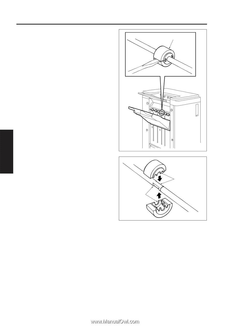
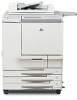
| 1.7 Removing and reinstalling of the main tray |
373 |
| 1.8 Removing and reinstalling of the main paper exit opening cover |
374 |
| 1.9 Removing and reinstalling of the booklet paper exit opening cover (Q5687A only) |
374 |
| 2. CONVEYANCE |
375 |
| 2.1 Replacing the paper exit roller A (sponge roller) |
375 |
| 2.2 Replacing the intermediate conveyance roller (sponge roller) |
377 |
| 2.3 Removing and reinstalling of the paper exit opening unit |
378 |
| 3. MAIN TRAY |
380 |
| 3.1 Replacing the tray up/down motor |
380 |
| 3.2 Removing and reinstalling of the up/down wire |
381 |
| 4. STACKER |
385 |
| 4.1 Replacing the stacking assist roller |
385 |
| 4.2 Removing and reinstalling of the stacker unit cover |
385 |
| 5. STAPLER |
389 |
| 5.1 Removing and reinstalling of the stapler unit cover |
389 |
| 5.2 Replacing the clincher |
390 |
| 5.3 Replacing the stapler |
392 |
| 2500-sheet High Capacity Input Q5690A |
395 |
| CONTENTS |
397 |
| I OUTLINE |
399 |
| 1. Q5690A PRODUCT SPECIFICATIONS |
399 |
| 2. CENTER CROSS SECTION |
400 |
| 3. DRIVE SYSTEM DIAGRAM |
401 |
| 3.1 Paper feed drive |
401 |
| 3.2 Up/down plate drive |
403 |
| II UNIT EXPLANATION |
405 |
| 1. PAPER FEED |
405 |
| 1.1 Composition |
405 |
| 1.2 Operation |
407 |
| III DISASSEMBLY/ASSEMBLY |
411 |
| 1. EXTERIOR |
411 |
| 1.1 Removing and reinstalling the front cover |
411 |
| 1.2 Removing and reinstalling the clutch replacement cover and the rear cover |
413 |
| 1.3 Removing and reinstalling the paper feed pick-up cover |
414 |
| 2. PAPER FEED |
415 |
| 2.1 Cleaning the paper dust removing brush |
415 |
| 2.2 Removing and reinstalling the paper feed unit |
416 |
| 2.3 Replacing the paper feed roller and the feed roller |
417 |
| 2.4 Replacing the double feed prevention roller Q5690A |
418 |
| 2.5 Replacing the paper feed clutch and the pre-registration clutch |
420 |
| 3. TRAY UP/DOWN |
421 |
| 3.1 Removing and reinstalling the rear drive |
421 |
| 3.2 Removing and reinstalling the up/down wire |
426 |
| Post insertion kit Q3636A |
435 |
| Contents |
437 |
| Post insertion overview |
439 |
| Post insertion kit (Q3636A) product specifications |
440 |
| Type |
440 |
| Functions |
440 |
| Copy paper |
440 |
| Power, weight, dimensions |
440 |
| Maintenance |
441 |
| Operating environment |
441 |
| Center cross section |
441 |
| Drive system diagram |
442 |
| Feeding process |
443 |
| Automatic sheet feeding (online operation) |
443 |
| Manual sheet feeding (offline operation) |
443 |
| Post insertion unit explanation |
445 |
| External section |
446 |
| Mechanisms |
446 |
| Interlock control |
446 |
| Paper feed unit |
447 |
| Composition |
447 |
| Mechanisms |
447 |
| Feed control |
448 |
| Post insertion disassembly/assembly |
455 |
| External section |
456 |
| Removing/reinstalling the external covers |
456 |
| Paper feed unit |
457 |
| Replacing the paper pick roller and pick roller |
457 |
| Replacing the double feed prevent roller and torque limiter |
458 |
| Index |
459 |
| Hole Punch kit (Q3689A, Q3635A, Q3690A, Q3691A) |
461 |
| Contents |
463 |
| Punch kit overview |
465 |
| Punch Kit product specifications |
466 |
| Type |
466 |
| Functions |
466 |
| Applicable paper |
466 |
| Punch kit data |
467 |
| Maintenance |
467 |
| Operating environment |
467 |
| Center cross-sectional view |
468 |
| Drive system diagram |
469 |
| Punch section |
469 |
| Moving section |
469 |
| Punching process |
470 |
| Movement of the standby position of the punch unit |
470 |
| Formation of a registration loop |
471 |
| Correction of the punch position |
472 |
| Punch |
472 |
| Punch kit unit explanation |
475 |
| Punch section |
476 |
| Composition |
476 |
| Mechanisms |
477 |
| Punch control |
477 |
| Punch waste box section |
480 |
| Composition |
480 |
| Mechanisms |
480 |
| Punch waste conveyance control |
481 |
| Punch kit disassembly/assembly |
483 |
| Punch section |
484 |
| Screws that should not be removed |
484 |
| Replacing the punch unit |
484 |
| Cleaning the punch edges and punch waste full PS (PS802) |
486 |
| Index |
487 |
| Trimmer Unit Q3224A |
489 |
| CONTENTS |
490 |
| OUTLINE |
491 |
| PRODUCT SPECIFICATIONS |
493 |
| CENTER CROSS-SECTIONAL VIEW |
494 |
| DRIVE SYSTEM DIAGRAM |
495 |
| [1] Conveyance Drive Section |
495 |
| [2] Stopper Drive/Stopper Release Drive Section |
495 |
| [3] Press Drive Section |
496 |
| [4] Pusher Plate Drive/Holder Plate Drive |
496 |
| TRIMMING PROCESS |
497 |
| [1] Booklet Conveyance |
497 |
| [2] Trimming Position Adjustment |
497 |
| [3] Booklet Press |
498 |
| [4] Trimming |
498 |
| [5] Press Release/Stopper Release |
499 |
| [6] Booklet Ejection |
499 |
| UNIT EXPLANATION |
501 |
| EXTERNAL SECTION |
503 |
| [1] Composition |
503 |
| [2] Mechanisms |
503 |
| CONVEYANCE SECTION |
504 |
| [1] Composition |
504 |
| [2] Mechanisms |
504 |
| [3] Conveyance Control |
504 |
| PRESS SECTION |
506 |
| [1] Composition |
506 |
| [2] Mechanisms |
506 |
| [3] Stopper/Press Control |
507 |
| TRIMMER SECTION |
510 |
| [1] Composition |
510 |
| [2] Mechanisms |
510 |
| [3] Trimmer Control |
511 |
| [4] Scraps Removal Control |
512 |
| STACKER SECTION |
513 |
| [1] Composition |
513 |
| [2] Mechanisms |
513 |
| [3] Booklet Ejection/Stack Control |
514 |
| DISASSEMBLY/ASSEMBLY |
517 |
| TRIMMER SECTION |
519 |
| [1] Replacing the Upper and Lower Knives |
519 |
 1
1 371
371 372
372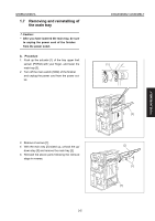 373
373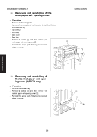 374
374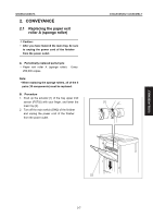 375
375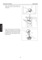 376
376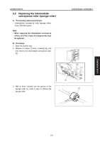 377
377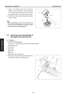 378
378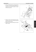 379
379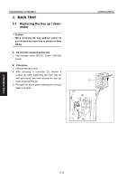 380
380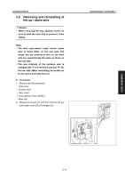 381
381