HP Color 9850mfp Service Manual - Page 477
Mechanisms, Punch control
 |
View all HP Color 9850mfp manuals
Add to My Manuals
Save this manual to your list of manuals |
Page 477 highlights
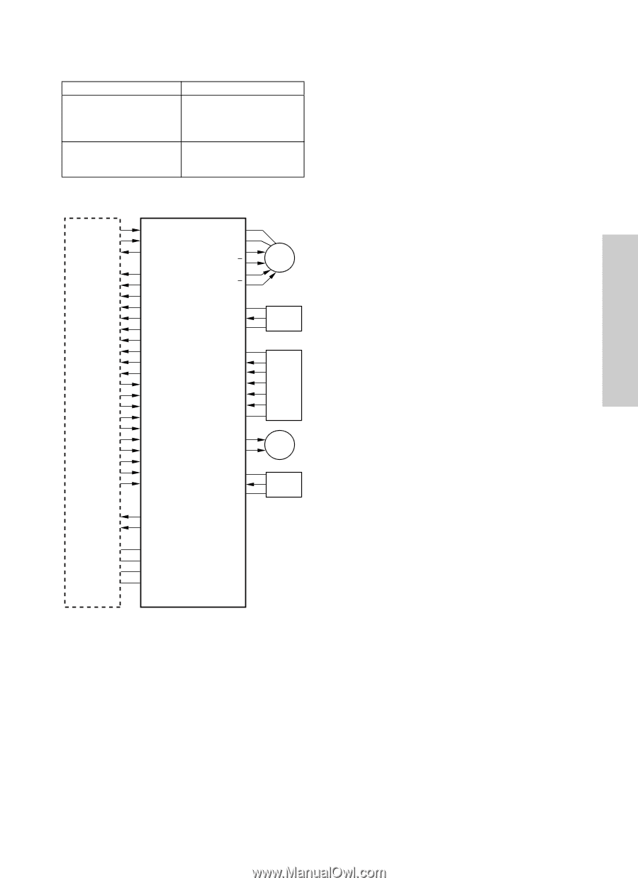
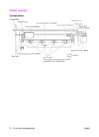
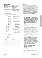
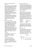
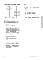
Punch kit unit explanation Mechanisms Mechanism Back-and-forth movement of punch unit Punch unit movement Method Punch motor (M801) Eccentric cam Drive arms Punch edges Punch shift motor (M802) Concurrent use of Gear / Rack Punch control M801 CONT M801 F/R SIG_1 SIG_2 SIG_3 SIG_4 SIG_5 SIG_6 SIG_7 SIG_8 SIG_9 SIG_10 PS801 OUT-1 OUT-2 OUT-3 OUT-4 OUT-5 OUT-6 OUT-7 OUT-8 OUT-9 OUT-10 24V 24V M802 DRVA M802 DRVA M802 DRVB M802 DRVB PS803 5V PS803 IN PS803 SG 5V IN1 IN2 IN3 IN4 IN5 SG M801 DRV1 M801 DRV2 PS801 5V PS801 IN PS801 SG M802 PS803 PAPER EDGE SENSOR M801 PS801 PKSET PKSET2 5V SG 24V PG FNS CB PKDB The movement of the punch unit is driven by M802 (punch shift) and the punching operation is driven by M801 (punch). M801 is DC motor, and rotates once per punch. Related signals are PS801 (punch HP), PS803 (punch shift HP), and paper edge sensor. 1 Operation The punching operation can be divided into the movement of the punch unit and the punch movement that makes holes. In the punch mode, these movements are performed for every sheet of paper, while in the non-punch mode these are not performed. However, the movement of the punch unit is performed for some paper sizes even in the non-punch mode. a Searching the standby home position of the punch unit With power turned on, M802 (punch shift) runs to move the punch unit to the position where PS803 (punch shift HP) is turned on, which makes a standby state. This position becomes the standby home position of the punch unit. b Moving the standby position of the punch unit When the punch mode is selected, M802 (punch shift) runs to move the punch unit so that the paper edge sensor mounted on the punch unit is located inside of the side edge of paper by 5 mm. However, if the paper size is Letter, Legal, or 5.5 by 8.5R, the sensor is positioned by 10 mm inside. Either of these positions becomes the standby position in the punch mode. The above operation is not generally performed in the non-punch mode, however, for the paper sizes shown below, the punch unit is moved to the position located inside of the side edge of paper by 10 mm in order to secure the easy feeding of paper when conveyed. 2 holes / 4 holes / Inch 2 holes / Swedish 4 holes MFPs: B6 / 16K 3 holes MFP: Letter / 8.5 by 14 / 5.5 by 8.5R / A5R / A4 ENWW Punch section 13
-
 1
1 -
2
-
3
-
4
-
5
-
6
-
7
-
8
-
9
-
10
-
11
-
12
-
13
-
14
-
15
-
16
-
17
-
18
-
19
-
20
-
21
-
22
-
23
-
24
-
25
-
26
-
27
-
28
-
29
-
30
-
31
-
32
-
33
-
34
-
35
-
36
-
37
-
38
-
39
-
40
-
41
-
42
-
43
-
44
-
45
-
46
-
47
-
48
-
49
-
50
-
51
-
52
-
53
-
54
-
55
-
56
-
57
-
58
-
59
-
60
-
61
-
62
-
63
-
64
-
65
-
66
-
67
-
68
-
69
-
70
-
71
-
72
-
73
-
74
-
75
-
76
-
77
-
78
-
79
-
80
-
81
-
82
-
83
-
84
-
85
-
86
-
87
-
88
-
89
-
90
-
91
-
92
-
93
-
94
-
95
-
96
-
97
-
98
-
99
-
100
-
101
-
102
-
103
-
104
-
105
-
106
-
107
-
108
-
109
-
110
-
111
-
112
-
113
-
114
-
115
-
116
-
117
-
118
-
119
-
120
-
121
-
122
-
123
-
124
-
125
-
126
-
127
-
128
-
129
-
130
-
131
-
132
-
133
-
134
-
135
-
136
-
137
-
138
-
139
-
140
-
141
-
142
-
143
-
144
-
145
-
146
-
147
-
148
-
149
-
150
-
151
-
152
-
153
-
154
-
155
-
156
-
157
-
158
-
159
-
160
-
161
-
162
-
163
-
164
-
165
-
166
-
167
-
168
-
169
-
170
-
171
-
172
-
173
-
174
-
175
-
176
-
177
-
178
-
179
-
180
-
181
-
182
-
183
-
184
-
185
-
186
-
187
-
188
-
189
-
190
-
191
-
192
-
193
-
194
-
195
-
196
-
197
-
198
-
199
-
200
-
201
-
202
-
203
-
204
-
205
-
206
-
207
-
208
-
209
-
210
-
211
-
212
-
213
-
214
-
215
-
216
-
217
-
218
-
219
-
220
-
221
-
222
-
223
-
224
-
225
-
226
-
227
-
228
-
229
-
230
-
231
-
232
-
233
-
234
-
235
-
236
-
237
-
238
-
239
-
240
-
241
-
242
-
243
-
244
-
245
-
246
-
247
-
248
-
249
-
250
-
251
-
252
-
253
-
254
-
255
-
256
-
257
-
258
-
259
-
260
-
261
-
262
-
263
-
264
-
265
-
266
-
267
-
268
-
269
-
270
-
271
-
272
-
273
-
274
-
275
-
276
-
277
-
278
-
279
-
280
-
281
-
282
-
283
-
284
-
285
-
286
-
287
-
288
-
289
-
290
-
291
-
292
-
293
-
294
-
295
-
296
-
297
-
298
-
299
-
300
-
301
-
302
-
303
-
304
-
305
-
306
-
307
-
308
-
309
-
310
-
311
-
312
-
313
-
314
-
315
-
316
-
317
-
318
-
319
-
320
-
321
-
322
-
323
-
324
-
325
-
326
-
327
-
328
-
329
-
330
-
331
-
332
-
333
-
334
-
335
-
336
-
337
-
338
-
339
-
340
-
341
-
342
-
343
-
344
-
345
-
346
-
347
-
348
-
349
-
350
-
351
-
352
-
353
-
354
-
355
-
356
-
357
-
358
-
359
-
360
-
361
-
362
-
363
-
364
-
365
-
366
-
367
-
368
-
369
-
370
-
371
-
372
-
373
-
374
-
375
-
376
-
377
-
378
-
379
-
380
-
381
-
382
-
383
-
384
-
385
-
386
-
387
-
388
-
389
-
390
-
391
-
392
-
393
-
394
-
395
-
396
-
397
-
398
-
399
-
400
-
401
-
402
-
403
-
404
-
405
-
406
-
407
-
408
-
409
-
410
-
411
-
412
-
413
-
414
-
415
-
416
-
417
-
418
-
419
-
420
-
421
-
422
-
423
-
424
-
425
-
426
-
427
-
428
-
429
-
430
-
431
-
432
-
433
-
434
-
435
-
436
-
437
-
438
-
439
-
440
-
441
-
442
-
443
-
444
-
445
-
446
-
447
-
448
-
449
-
450
-
451
-
452
-
453
-
454
-
455
-
456
-
457
-
458
-
459
-
460
-
461
-
462
-
463
-
464
-
465
-
466
-
467
-
468
-
469
-
470
-
471
-
 472
472 -
 473
473 -
 474
474 -
 475
475 -
 476
476 -
 477
477 -
 478
478 -
 479
479 -
 480
480 -
 481
481 -
 482
482 -
483
-
484
-
485
-
486
-
487
-
488
-
489
-
490
-
491
-
492
-
493
-
494
-
495
-
496
-
497
-
498
-
499
-
500
-
501
-
502
-
503
-
504
-
505
-
506
-
507
-
508
-
509
-
510
-
511
-
512
-
513
-
514
-
515
-
516
-
517
-
518
-
519
-
520
-
521
-
522
 |
 |