HP FAX-750 Service Manual - Page 17
The control electronics deactivates the solenoid and rotates the motor clockwise to drive the platen - ink
 |
View all HP FAX-750 manuals
Add to My Manuals
Save this manual to your list of manuals |
Page 17 highlights
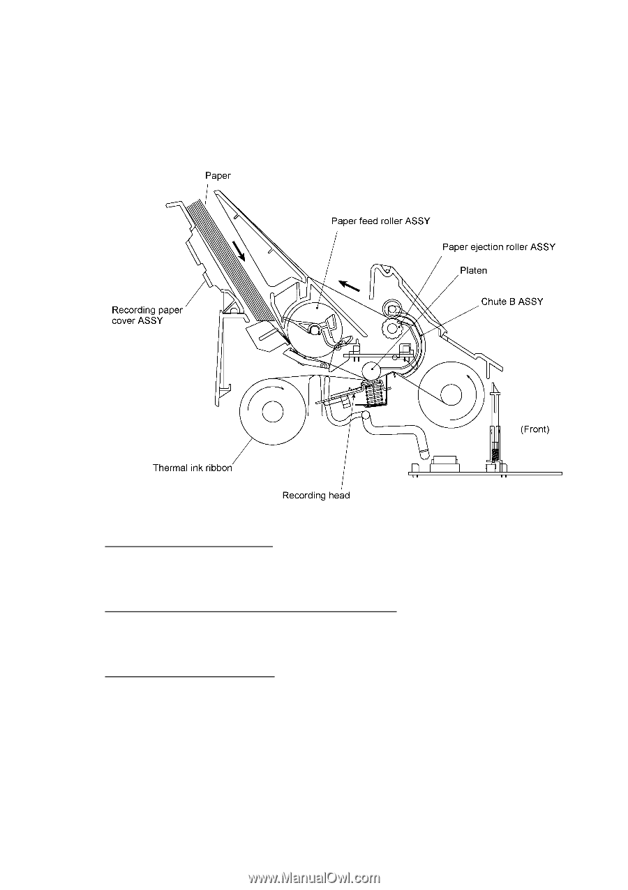
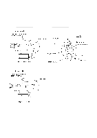
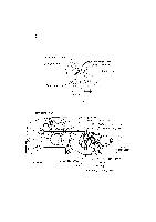
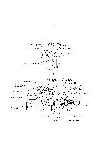
2.2 Receiving Mechanism (Feeding paper and printing data) The receiving mechanism consists of the recording paper cover ASSY, paper feed roller ASSY, platen, thermal recording head, paper ejection roller, and sensors. (For details about the sensors, refer to Section 2.4.) STEP 1: In the paper feeding mode If the equipment receives data, the control electronics activates the solenoid and rotates the motor counterclockwise to drive the paper feed roller (and paper ejection roller). This pulls in a sheet of paper and feeds it until its leading edge reaches the point just before the printing position. STEP 2: In the recording (platen drive & ribbon take-up) mode The control electronics deactivates the solenoid and rotates the motor clockwise to drive the platen gear and the ribbon take-up gear as well as the paper ejection roller. This feeds the paper up to the printing position where the thermal recording head prints, as well as feeding the thermal ink ribbon. STEP 3: In the paper ejection mode The same operation as for STEP 1 takes place so as to eject the paper. III - 4
-
 1
1 -
2
-
3
-
4
-
5
-
6
-
7
-
8
-
9
-
10
-
11
-
 12
12 -
 13
13 -
 14
14 -
 15
15 -
 16
16 -
 17
17 -
 18
18 -
 19
19 -
 20
20 -
 21
21 -
 22
22 -
23
-
24
-
25
-
26
-
27
-
28
-
29
-
30
-
31
-
32
-
33
-
34
-
35
-
36
-
37
-
38
-
39
-
40
-
41
-
42
-
43
-
44
-
45
-
46
-
47
-
48
-
49
-
50
-
51
-
52
-
53
-
54
-
55
-
56
-
57
-
58
-
59
-
60
-
61
-
62
-
63
-
64
-
65
-
66
-
67
-
68
-
69
-
70
-
71
-
72
-
73
-
74
-
75
-
76
-
77
-
78
-
79
-
80
-
81
-
82
-
83
-
84
-
85
-
86
-
87
-
88
-
89
-
90
-
91
-
92
-
93
-
94
-
95
-
96
-
97
-
98
-
99
-
100
-
101
-
102
-
103
-
104
-
105
-
106
-
107
-
108
-
109
-
110
-
111
-
112
-
113
-
114
-
115
-
116
-
117
-
118
-
119
-
120
-
121
-
122
-
123
-
124
-
125
-
126
-
127
-
128
-
129
-
130
-
131
-
132
-
133
-
134
-
135
-
136
-
137
-
138
-
139
-
140
-
141
-
142
-
143
-
144
-
145
-
146
-
147
-
148
-
149
-
150
-
151
-
152
-
153
-
154
-
155
-
156
-
157
-
158
-
159
-
160
-
161
-
162
-
163
-
164
-
165
-
166
-
167
-
168
-
169
-
170
-
171
-
172
-
173
-
174
-
175
-
176
-
177
-
178
-
179
-
180
-
181
-
182
-
183
-
184
-
185
-
186
-
187
-
188
-
189
-
190
-
191
-
192
-
193
-
194
-
195
-
196
-
197
-
198
-
199
-
200
-
201
-
202
-
203
-
204
-
205
-
206
-
207
-
208
-
209
-
210
-
211
-
212
-
213
-
214
-
215
-
216
-
217
-
218
 |
 |