HP FAX-750 Service Manual - Page 25
Copying mode Solenoid: ON, Motor rotation: Forward
 |
View all HP FAX-750 manuals
Add to My Manuals
Save this manual to your list of manuals |
Page 25 highlights
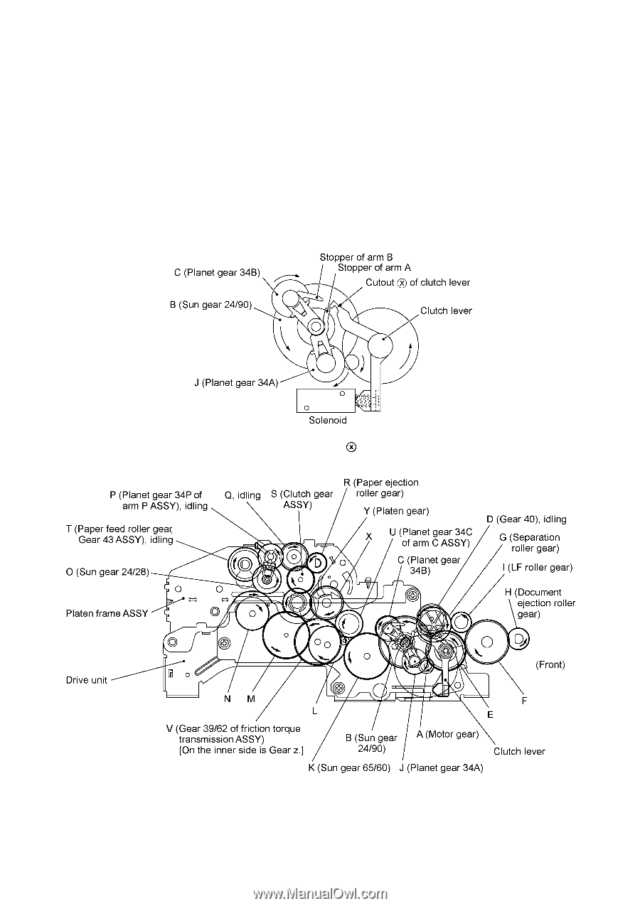
[ 4 ] Copying mode (Solenoid: ON, Motor rotation: Forward) In the copying mode, the control electronics activates the solenoid to release the stopper of arm A from the clutch lever. When the motor rotates in the forward direction, sun gear 24/90 ("B") rotates counterclockwise so that planet gear 34A ("J") transmits the torque to the document scanner mechanism (e.g., the separation roller gear ("G"), LF roller gear ("I") and document ejection roller gear ("H")) and planet gear 34B ("C") transmits the torque to the recording mechanism (e.g., platen gear ("Y") and paper ejection roller gear ("R")). If gear 39/62 ("V") rotates, gear 20 ("z") on the inner side of the drive unit also rotates so as to drive the friction torque transmission ASSY and ribbon drive gear ("w") that rotates ribbon take-up gear ("a") on the ribbon cartridge, as shown on the next page. Arm A Released from Cutout of Clutch Lever Active Gears on the Outer Side of the Drive Unit and on the Left Sides of the Platen Frame, Main Frame and Control Panel ASSY III - 12
-
 1
1 -
2
-
3
-
4
-
5
-
6
-
7
-
8
-
9
-
10
-
11
-
12
-
13
-
14
-
15
-
16
-
17
-
18
-
19
-
 20
20 -
 21
21 -
 22
22 -
 23
23 -
 24
24 -
 25
25 -
 26
26 -
 27
27 -
 28
28 -
 29
29 -
 30
30 -
31
-
32
-
33
-
34
-
35
-
36
-
37
-
38
-
39
-
40
-
41
-
42
-
43
-
44
-
45
-
46
-
47
-
48
-
49
-
50
-
51
-
52
-
53
-
54
-
55
-
56
-
57
-
58
-
59
-
60
-
61
-
62
-
63
-
64
-
65
-
66
-
67
-
68
-
69
-
70
-
71
-
72
-
73
-
74
-
75
-
76
-
77
-
78
-
79
-
80
-
81
-
82
-
83
-
84
-
85
-
86
-
87
-
88
-
89
-
90
-
91
-
92
-
93
-
94
-
95
-
96
-
97
-
98
-
99
-
100
-
101
-
102
-
103
-
104
-
105
-
106
-
107
-
108
-
109
-
110
-
111
-
112
-
113
-
114
-
115
-
116
-
117
-
118
-
119
-
120
-
121
-
122
-
123
-
124
-
125
-
126
-
127
-
128
-
129
-
130
-
131
-
132
-
133
-
134
-
135
-
136
-
137
-
138
-
139
-
140
-
141
-
142
-
143
-
144
-
145
-
146
-
147
-
148
-
149
-
150
-
151
-
152
-
153
-
154
-
155
-
156
-
157
-
158
-
159
-
160
-
161
-
162
-
163
-
164
-
165
-
166
-
167
-
168
-
169
-
170
-
171
-
172
-
173
-
174
-
175
-
176
-
177
-
178
-
179
-
180
-
181
-
182
-
183
-
184
-
185
-
186
-
187
-
188
-
189
-
190
-
191
-
192
-
193
-
194
-
195
-
196
-
197
-
198
-
199
-
200
-
201
-
202
-
203
-
204
-
205
-
206
-
207
-
208
-
209
-
210
-
211
-
212
-
213
-
214
-
215
-
216
-
217
-
218
 |
 |