HP FAX-750 Service Manual - Page 73
Refer to CAUTION, Reassembling Notes
 |
View all HP FAX-750 manuals
Add to My Manuals
Save this manual to your list of manuals |
Page 73 highlights
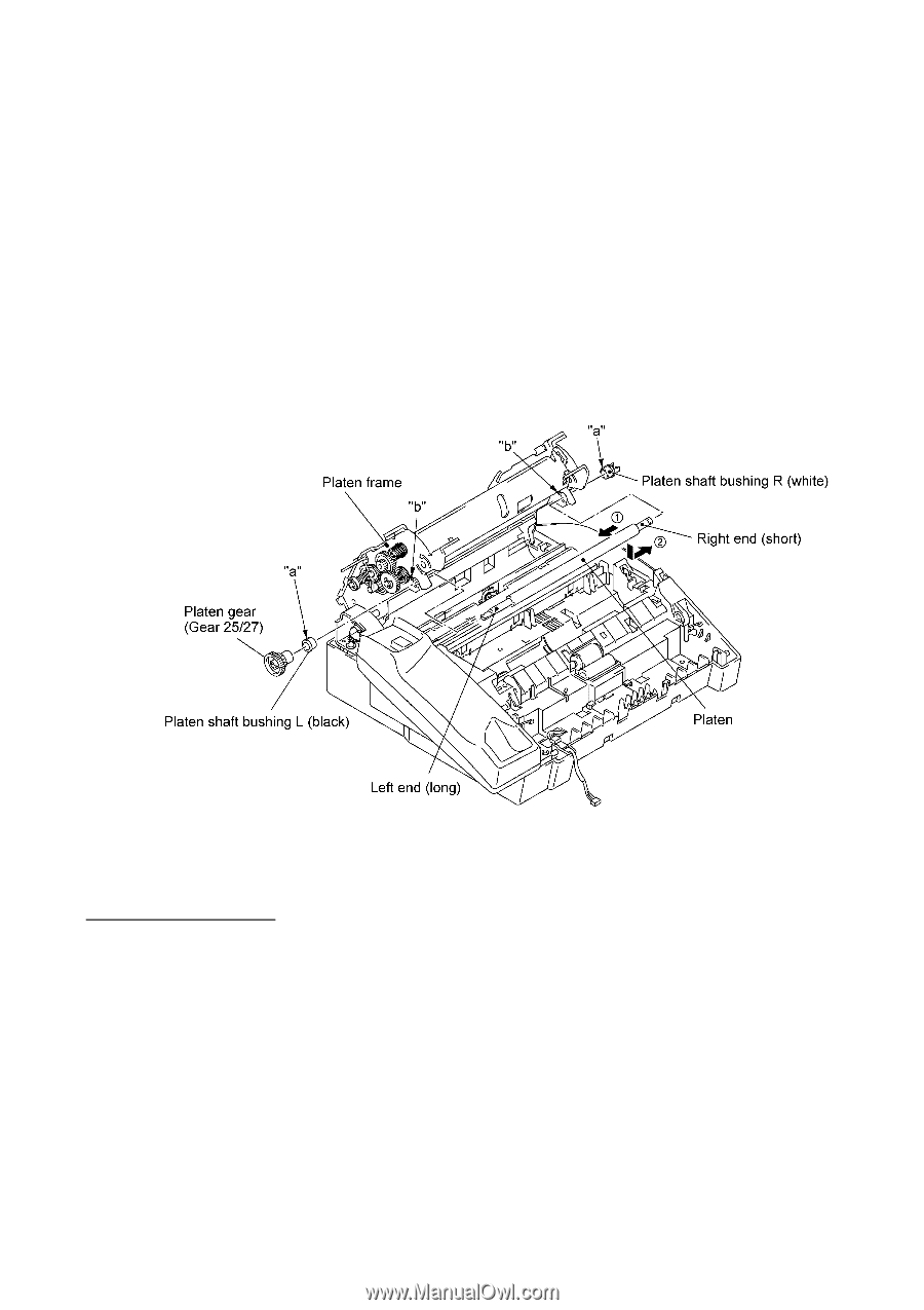
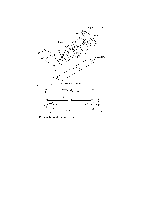
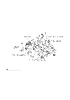
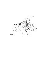
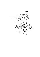
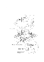
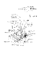
(16) Remove the platen as follows: At the left end of the platen frame, remove the platen gear (gear 25/27) by pulling its pawl outwards and then remove the platen shaft bushing L. At the right end, remove the platen shaft bushing R by pulling its pawls outwards. Move the platen to the left to take out the right end from the platen frame and then take it out to the right. CAUTION: After removing the platen, NEVER close the platen frame ASSY when the recording head ASSY is set in place. Doing so will make the cutouts of the platen frame ASSY catch the right and left ends of the recording head ASSY. The platen frame ASSY and the recording head ASSY will be locked together. NOTE: The platen shaft bushings are greased for antistatic purpose. Take care not to stain other parts with the grease. n Reassembling Notes • If you replace the platen shaft bushing(s) with new one(s), apply grease to it. (Refer to Section 2, "LUBRICATION." • When reinstalling the platen shaft bushings R and L, fit boss "a" of each bushing into cutout "b" provided in the platen frame. (See the above illustration.) • When attaching the chute film, align its rear edge with the rib of the paper feed chute. • When reinstalling the pressure plate, slide the ribs along the grooves of the paper feed chute until the latches of the pressure plate catch the pressure plate link. • When setting the lock levers back into place, as shown on page IV-23, first fit the shorter end of the spring into the cutout provided in each lock lever, then fit the longer end of the spring and the lock lever's boss into the small and large holes provided in the platen frame, respectively. Fully turn the lever to the rear so that the lever's hooks catch the platen frame. IV - 33
-
 1
1 -
2
-
3
-
4
-
5
-
6
-
7
-
8
-
9
-
10
-
11
-
12
-
13
-
14
-
15
-
16
-
17
-
18
-
19
-
20
-
21
-
22
-
23
-
24
-
25
-
26
-
27
-
28
-
29
-
30
-
31
-
32
-
33
-
34
-
35
-
36
-
37
-
38
-
39
-
40
-
41
-
42
-
43
-
44
-
45
-
46
-
47
-
48
-
49
-
50
-
51
-
52
-
53
-
54
-
55
-
56
-
57
-
58
-
59
-
60
-
61
-
62
-
63
-
64
-
65
-
66
-
67
-
 68
68 -
 69
69 -
 70
70 -
 71
71 -
 72
72 -
 73
73 -
 74
74 -
 75
75 -
 76
76 -
 77
77 -
 78
78 -
79
-
80
-
81
-
82
-
83
-
84
-
85
-
86
-
87
-
88
-
89
-
90
-
91
-
92
-
93
-
94
-
95
-
96
-
97
-
98
-
99
-
100
-
101
-
102
-
103
-
104
-
105
-
106
-
107
-
108
-
109
-
110
-
111
-
112
-
113
-
114
-
115
-
116
-
117
-
118
-
119
-
120
-
121
-
122
-
123
-
124
-
125
-
126
-
127
-
128
-
129
-
130
-
131
-
132
-
133
-
134
-
135
-
136
-
137
-
138
-
139
-
140
-
141
-
142
-
143
-
144
-
145
-
146
-
147
-
148
-
149
-
150
-
151
-
152
-
153
-
154
-
155
-
156
-
157
-
158
-
159
-
160
-
161
-
162
-
163
-
164
-
165
-
166
-
167
-
168
-
169
-
170
-
171
-
172
-
173
-
174
-
175
-
176
-
177
-
178
-
179
-
180
-
181
-
182
-
183
-
184
-
185
-
186
-
187
-
188
-
189
-
190
-
191
-
192
-
193
-
194
-
195
-
196
-
197
-
198
-
199
-
200
-
201
-
202
-
203
-
204
-
205
-
206
-
207
-
208
-
209
-
210
-
211
-
212
-
213
-
214
-
215
-
216
-
217
-
218
 |
 |