HP FAX-750 Service Manual - Page 18
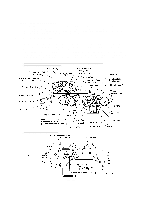
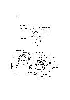
The rotational torque is further transmitted to the, on the inner side of the drive unit also rotates. - cartridges
 |
View all HP FAX-750 manuals
Add to My Manuals
Save this manual to your list of manuals |
Page 18 highlights
2.3 Power Transmission Mechanism The equipment has a single drive motor whose power transmission route can be switched by the planetary gear systems and the solenoid. This switching allows the equipment to function in four operation modes (scanning, paper feeding/ejecting, recording, and copying modes). For the details about the planetary gear systems, refer to Subsection 2.3.2. 2.3.1 Structure of the gear train All of the motor and gears are located at the left side of the equipment. As illustrated in the figure below (On the outer side of the drive unit), the rotational torque of the motor on the drive unit is transmitted via the gears on the drive unit to the gears on the main frame, to those on the control panel ASSY, and to those on the platen frame. If gear 39/62 of the friction torque transmission ASSY ("V" in the figure below) rotates, gear 20 ("z") on the inner side of the drive unit also rotates. The rotational torque is further transmitted to the ribbon drive gear ("w") which drives the ribbon take-up gear ("a") on the ribbon cartridge, as shown in the figure below (On the inner side of the drive unit). On the outer side of the drive unit and on the left sides of the platen frame, main frame and control panel ASSY On the inner side of the drive unit Gear Train III - 5
-
 1
1 -
2
-
3
-
4
-
5
-
6
-
7
-
8
-
9
-
10
-
11
-
12
-
 13
13 -
 14
14 -
 15
15 -
 16
16 -
 17
17 -
 18
18 -
 19
19 -
 20
20 -
 21
21 -
 22
22 -
 23
23 -
24
-
25
-
26
-
27
-
28
-
29
-
30
-
31
-
32
-
33
-
34
-
35
-
36
-
37
-
38
-
39
-
40
-
41
-
42
-
43
-
44
-
45
-
46
-
47
-
48
-
49
-
50
-
51
-
52
-
53
-
54
-
55
-
56
-
57
-
58
-
59
-
60
-
61
-
62
-
63
-
64
-
65
-
66
-
67
-
68
-
69
-
70
-
71
-
72
-
73
-
74
-
75
-
76
-
77
-
78
-
79
-
80
-
81
-
82
-
83
-
84
-
85
-
86
-
87
-
88
-
89
-
90
-
91
-
92
-
93
-
94
-
95
-
96
-
97
-
98
-
99
-
100
-
101
-
102
-
103
-
104
-
105
-
106
-
107
-
108
-
109
-
110
-
111
-
112
-
113
-
114
-
115
-
116
-
117
-
118
-
119
-
120
-
121
-
122
-
123
-
124
-
125
-
126
-
127
-
128
-
129
-
130
-
131
-
132
-
133
-
134
-
135
-
136
-
137
-
138
-
139
-
140
-
141
-
142
-
143
-
144
-
145
-
146
-
147
-
148
-
149
-
150
-
151
-
152
-
153
-
154
-
155
-
156
-
157
-
158
-
159
-
160
-
161
-
162
-
163
-
164
-
165
-
166
-
167
-
168
-
169
-
170
-
171
-
172
-
173
-
174
-
175
-
176
-
177
-
178
-
179
-
180
-
181
-
182
-
183
-
184
-
185
-
186
-
187
-
188
-
189
-
190
-
191
-
192
-
193
-
194
-
195
-
196
-
197
-
198
-
199
-
200
-
201
-
202
-
203
-
204
-
205
-
206
-
207
-
208
-
209
-
210
-
211
-
212
-
213
-
214
-
215
-
216
-
217
-
218
 |
 |
