HP FAX-750 Service Manual - Page 77
The FAX870MC/FAX-930/FAX-931/MFC970MC has a Ni-MH battery ASSY., Power Supply PCB, Main PCB
 |
View all HP FAX-750 manuals
Add to My Manuals
Save this manual to your list of manuals |
Page 77 highlights
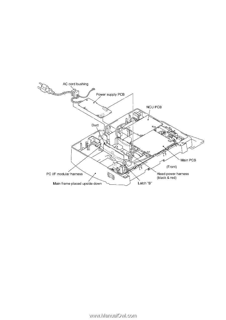
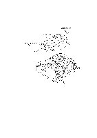
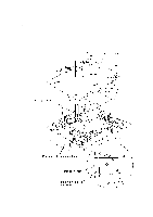
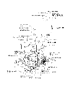
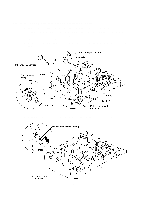
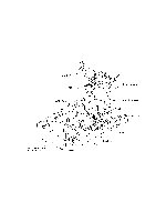
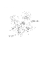
1.10 Power Supply PCB, Main PCB, and NCU PCB (1) Unhook the head-power harness from latch "B" (together with the PC I/F modular harness since the head-power harness is routed under the PC I/F modular harness through the duct when viewed from the bottom). (2) Pull out the AC cord bushing from the main frame. (3) Disconnect the power supply PCB from the main PCB. (4) Slightly lift up the power supply PCB and disconnect the head-power harness. (5) Slightly lift up the main PCB and NCU PCB together, then disconnect the NCU PCB from the main PCB. (6) Disconnect the following nine harnesses from the main PCB: • Hook switch harness (Not provided on the FAX-910.) • Speaker harness • Panel-main harness • PC I/F modular harness • CIS harness • Solenoid harness • Motor harness • Main-head harness • Main-sensor harness NOTE: The FAX870MC/FAX-930/FAX-931/MFC970MC has a Ni-MH battery ASSY. Only when you need to replace the main PCB, disconnect the battery harness. After installing a new main PCB, you may need to make settings to be stored in the RAM. If you need to replace the battery ASSY, do not disconnect the harness in this disassembly step. Doing so with the power cord unplugged will lose the settings stored in the RAM. Refer to Section 1.1. (7) You may take out the harnesses (except for the main-head harness that is routed under the drive unit) from the main frame. IV - 37
-
 1
1 -
2
-
3
-
4
-
5
-
6
-
7
-
8
-
9
-
10
-
11
-
12
-
13
-
14
-
15
-
16
-
17
-
18
-
19
-
20
-
21
-
22
-
23
-
24
-
25
-
26
-
27
-
28
-
29
-
30
-
31
-
32
-
33
-
34
-
35
-
36
-
37
-
38
-
39
-
40
-
41
-
42
-
43
-
44
-
45
-
46
-
47
-
48
-
49
-
50
-
51
-
52
-
53
-
54
-
55
-
56
-
57
-
58
-
59
-
60
-
61
-
62
-
63
-
64
-
65
-
66
-
67
-
68
-
69
-
70
-
71
-
 72
72 -
 73
73 -
 74
74 -
 75
75 -
 76
76 -
 77
77 -
 78
78 -
 79
79 -
 80
80 -
 81
81 -
 82
82 -
83
-
84
-
85
-
86
-
87
-
88
-
89
-
90
-
91
-
92
-
93
-
94
-
95
-
96
-
97
-
98
-
99
-
100
-
101
-
102
-
103
-
104
-
105
-
106
-
107
-
108
-
109
-
110
-
111
-
112
-
113
-
114
-
115
-
116
-
117
-
118
-
119
-
120
-
121
-
122
-
123
-
124
-
125
-
126
-
127
-
128
-
129
-
130
-
131
-
132
-
133
-
134
-
135
-
136
-
137
-
138
-
139
-
140
-
141
-
142
-
143
-
144
-
145
-
146
-
147
-
148
-
149
-
150
-
151
-
152
-
153
-
154
-
155
-
156
-
157
-
158
-
159
-
160
-
161
-
162
-
163
-
164
-
165
-
166
-
167
-
168
-
169
-
170
-
171
-
172
-
173
-
174
-
175
-
176
-
177
-
178
-
179
-
180
-
181
-
182
-
183
-
184
-
185
-
186
-
187
-
188
-
189
-
190
-
191
-
192
-
193
-
194
-
195
-
196
-
197
-
198
-
199
-
200
-
201
-
202
-
203
-
204
-
205
-
206
-
207
-
208
-
209
-
210
-
211
-
212
-
213
-
214
-
215
-
216
-
217
-
218
 |
 |