HP FAX-750 Service Manual - Page 51
Remove the screw from the document front sensor PCB., and moving it in the direction of arrow
 |
View all HP FAX-750 manuals
Add to My Manuals
Save this manual to your list of manuals |
Page 51 highlights
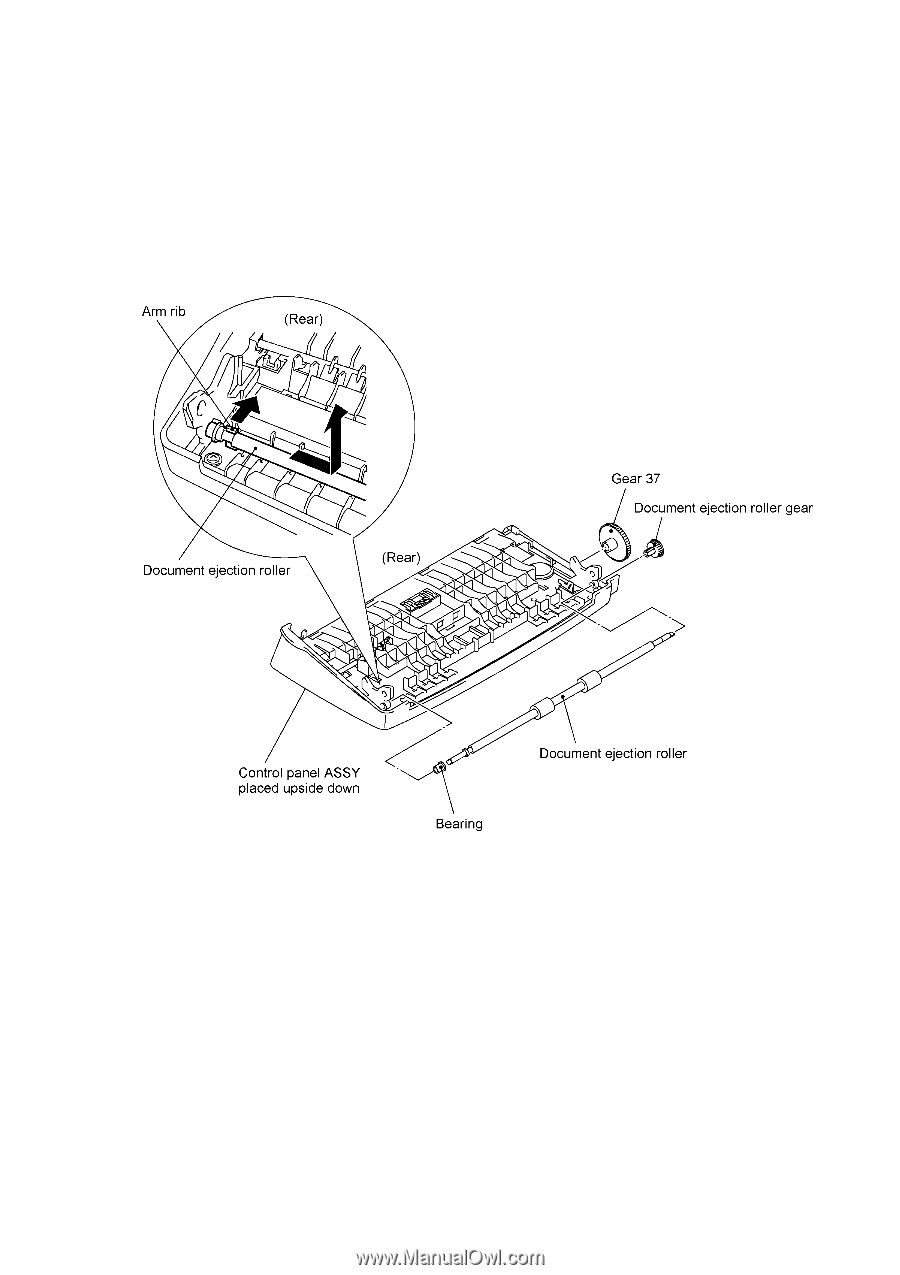
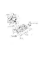
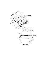
(5) To remove the document ejection roller, push the arm rib to the rear and shift the document ejection roller to the right. Pull out the document ejection roller gear and remove gear 37. Pull out the document ejection roller to the left. Remove the bearing. (6) Remove the two screws from the panel rear cover. (See the next page.) (7) Unhook the panel rear cover from the four "X" latches provided on the control panel and lift up the panel rear cover. (8) Remove the document front sensor actuator from the panel rear cover by turning it clockwise (in the direction of arrow •) and moving it in the direction of arrow ,. (9) Remove the screw from the document front sensor PCB. (10) FAX750/FAX770/FAX-910/FAX-920/FAX-921/MFC-925: Unhook the control panel PCB from the two "Y" latches. FAX870MC/FAX-930/FAX-931/MFC970MC: Remove the screw from the control panel PCB and unhook the PCB from the two "Y" latches. Disconnect the microphone. IV - 11
-
 1
1 -
2
-
3
-
4
-
5
-
6
-
7
-
8
-
9
-
10
-
11
-
12
-
13
-
14
-
15
-
16
-
17
-
18
-
19
-
20
-
21
-
22
-
23
-
24
-
25
-
26
-
27
-
28
-
29
-
30
-
31
-
32
-
33
-
34
-
35
-
36
-
37
-
38
-
39
-
40
-
41
-
42
-
43
-
44
-
45
-
 46
46 -
 47
47 -
 48
48 -
 49
49 -
 50
50 -
 51
51 -
 52
52 -
 53
53 -
 54
54 -
 55
55 -
 56
56 -
57
-
58
-
59
-
60
-
61
-
62
-
63
-
64
-
65
-
66
-
67
-
68
-
69
-
70
-
71
-
72
-
73
-
74
-
75
-
76
-
77
-
78
-
79
-
80
-
81
-
82
-
83
-
84
-
85
-
86
-
87
-
88
-
89
-
90
-
91
-
92
-
93
-
94
-
95
-
96
-
97
-
98
-
99
-
100
-
101
-
102
-
103
-
104
-
105
-
106
-
107
-
108
-
109
-
110
-
111
-
112
-
113
-
114
-
115
-
116
-
117
-
118
-
119
-
120
-
121
-
122
-
123
-
124
-
125
-
126
-
127
-
128
-
129
-
130
-
131
-
132
-
133
-
134
-
135
-
136
-
137
-
138
-
139
-
140
-
141
-
142
-
143
-
144
-
145
-
146
-
147
-
148
-
149
-
150
-
151
-
152
-
153
-
154
-
155
-
156
-
157
-
158
-
159
-
160
-
161
-
162
-
163
-
164
-
165
-
166
-
167
-
168
-
169
-
170
-
171
-
172
-
173
-
174
-
175
-
176
-
177
-
178
-
179
-
180
-
181
-
182
-
183
-
184
-
185
-
186
-
187
-
188
-
189
-
190
-
191
-
192
-
193
-
194
-
195
-
196
-
197
-
198
-
199
-
200
-
201
-
202
-
203
-
204
-
205
-
206
-
207
-
208
-
209
-
210
-
211
-
212
-
213
-
214
-
215
-
216
-
217
-
218
 |
 |