HP FAX-750 Service Manual - Page 98
Printout of Scanning Compensation Data, Function, Operating Procedure
 |
View all HP FAX-750 manuals
Add to My Manuals
Save this manual to your list of manuals |
Page 98 highlights
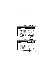
3.2 Printout of Scanning Compensation Data n Function The equipment prints out the white and black level data for scanning compensation. n Operating Procedure Do not start this function merely after powering on the equipment but start it after carrying out a sequence of scanning operation. Unless the equipment has carried out any scanning operation, this function cannot print out correct scanning compensation data. This is because at the start of scanning operation, the equipment initializes white and black level data and takes in the scanning compensation reference data. (1) Press the 0 and 5 keys in this order in the initial stage of the maintenance mode. The "WHITE LEVEL 1" will appear on the LCD. (2) The equipment prints out the scanning compensation data list containing the following: a) White level data (208 bytes) b) Black level data (1 byte) c) Initial clamp PWM value (1 byte) d) Clamp PWM value (1 byte) e) Compensation data for background color (1 byte) f) Initial LED light intensity value (1 byte) g) LED light intensity value (1 byte) h) LED light intensity value on the white film of the document pressure bar ASSY and documents (2 bytes) i) Document rear sensor adjustment value (1 byte) (3) Upon completion of recording of the compensation data list, the equipment returns to the initial stage of the maintenance mode. NOTE: If any data is abnormal, its code will be printed in inline style, as shown on the next page. V - 5
-
 1
1 -
2
-
3
-
4
-
5
-
6
-
7
-
8
-
9
-
10
-
11
-
12
-
13
-
14
-
15
-
16
-
17
-
18
-
19
-
20
-
21
-
22
-
23
-
24
-
25
-
26
-
27
-
28
-
29
-
30
-
31
-
32
-
33
-
34
-
35
-
36
-
37
-
38
-
39
-
40
-
41
-
42
-
43
-
44
-
45
-
46
-
47
-
48
-
49
-
50
-
51
-
52
-
53
-
54
-
55
-
56
-
57
-
58
-
59
-
60
-
61
-
62
-
63
-
64
-
65
-
66
-
67
-
68
-
69
-
70
-
71
-
72
-
73
-
74
-
75
-
76
-
77
-
78
-
79
-
80
-
81
-
82
-
83
-
84
-
85
-
86
-
87
-
88
-
89
-
90
-
91
-
92
-
 93
93 -
 94
94 -
 95
95 -
 96
96 -
 97
97 -
 98
98 -
 99
99 -
 100
100 -
 101
101 -
 102
102 -
 103
103 -
104
-
105
-
106
-
107
-
108
-
109
-
110
-
111
-
112
-
113
-
114
-
115
-
116
-
117
-
118
-
119
-
120
-
121
-
122
-
123
-
124
-
125
-
126
-
127
-
128
-
129
-
130
-
131
-
132
-
133
-
134
-
135
-
136
-
137
-
138
-
139
-
140
-
141
-
142
-
143
-
144
-
145
-
146
-
147
-
148
-
149
-
150
-
151
-
152
-
153
-
154
-
155
-
156
-
157
-
158
-
159
-
160
-
161
-
162
-
163
-
164
-
165
-
166
-
167
-
168
-
169
-
170
-
171
-
172
-
173
-
174
-
175
-
176
-
177
-
178
-
179
-
180
-
181
-
182
-
183
-
184
-
185
-
186
-
187
-
188
-
189
-
190
-
191
-
192
-
193
-
194
-
195
-
196
-
197
-
198
-
199
-
200
-
201
-
202
-
203
-
204
-
205
-
206
-
207
-
208
-
209
-
210
-
211
-
212
-
213
-
214
-
215
-
216
-
217
-
218
 |
 |