HP FAX-750 Service Manual - Page 53
surface with a soft cloth., Before reinstalling the control panel PCB to the control panel
 |
View all HP FAX-750 manuals
Add to My Manuals
Save this manual to your list of manuals |
Page 53 highlights
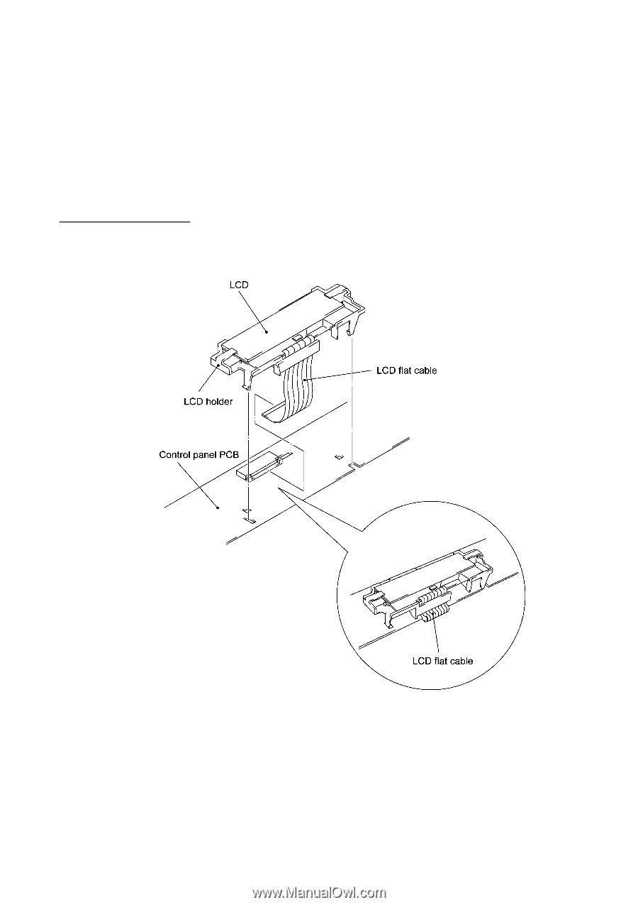
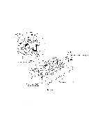
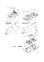
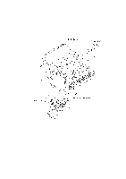
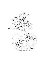
(11) To remove the LCD, unhook the four "Z" latches of the LCD holder from the control panel PCB. Unlock the LCD cable connector and disconnect the LCD flat cable. Slide the LCD to the cable side and remove it from the LCD holder. NOTE: Do not take out the LCD except when the LCD is defective and requires replacement. (12) Unlock the FPC key connector and disconnect the FPC key. n Reassembling Notes • A new LCD is covered with a protection sheet. Before installing it, remove the protection sheet. • As shown below, route the LCD flat cable and set the LCD holder on the control panel PCB. • Before reinstalling the control panel PCB to the control panel, wipe fingerprints off the LCD surface with a soft cloth. • After assembling the document pressure bar and its support together, check that the boss of the document pressure bar is fitted in the hole provided in the support. • After reinstalling the assembly of the document pressure bar and its support to the control panel ASSY, attach the white film, referring to the illustration given on page IV-10. IV - 13
-
 1
1 -
2
-
3
-
4
-
5
-
6
-
7
-
8
-
9
-
10
-
11
-
12
-
13
-
14
-
15
-
16
-
17
-
18
-
19
-
20
-
21
-
22
-
23
-
24
-
25
-
26
-
27
-
28
-
29
-
30
-
31
-
32
-
33
-
34
-
35
-
36
-
37
-
38
-
39
-
40
-
41
-
42
-
43
-
44
-
45
-
46
-
47
-
 48
48 -
 49
49 -
 50
50 -
 51
51 -
 52
52 -
 53
53 -
 54
54 -
 55
55 -
 56
56 -
 57
57 -
 58
58 -
59
-
60
-
61
-
62
-
63
-
64
-
65
-
66
-
67
-
68
-
69
-
70
-
71
-
72
-
73
-
74
-
75
-
76
-
77
-
78
-
79
-
80
-
81
-
82
-
83
-
84
-
85
-
86
-
87
-
88
-
89
-
90
-
91
-
92
-
93
-
94
-
95
-
96
-
97
-
98
-
99
-
100
-
101
-
102
-
103
-
104
-
105
-
106
-
107
-
108
-
109
-
110
-
111
-
112
-
113
-
114
-
115
-
116
-
117
-
118
-
119
-
120
-
121
-
122
-
123
-
124
-
125
-
126
-
127
-
128
-
129
-
130
-
131
-
132
-
133
-
134
-
135
-
136
-
137
-
138
-
139
-
140
-
141
-
142
-
143
-
144
-
145
-
146
-
147
-
148
-
149
-
150
-
151
-
152
-
153
-
154
-
155
-
156
-
157
-
158
-
159
-
160
-
161
-
162
-
163
-
164
-
165
-
166
-
167
-
168
-
169
-
170
-
171
-
172
-
173
-
174
-
175
-
176
-
177
-
178
-
179
-
180
-
181
-
182
-
183
-
184
-
185
-
186
-
187
-
188
-
189
-
190
-
191
-
192
-
193
-
194
-
195
-
196
-
197
-
198
-
199
-
200
-
201
-
202
-
203
-
204
-
205
-
206
-
207
-
208
-
209
-
210
-
211
-
212
-
213
-
214
-
215
-
216
-
217
-
218
 |
 |