HP LaserJet P4510 Service Manual
HP LaserJet P4510 Manual
 |
View all HP LaserJet P4510 manuals
Add to My Manuals
Save this manual to your list of manuals |
HP LaserJet P4510 manual content summary:
- HP LaserJet P4510 | Service Manual - Page 1
HP LaserJet P4010 and P4510 Series Printers Service Manual - HP LaserJet P4510 | Service Manual - Page 2
- HP LaserJet P4510 | Service Manual - Page 3
HP LaserJet P4010 and P4510 Series Printers Service Manual - HP LaserJet P4510 | Service Manual - Page 4
are set forth in the express warranty statements accompanying such products and services. Nothing herein should be construed as constituting an additional warranty. HP shall not be liable for technical or editorial errors or omissions contained herein. Part number: CB506-91004 Edition 1, 8/2008 - HP LaserJet P4510 | Service Manual - Page 5
14 HP Printer Utility 14 Supported printer drivers 16 Supported printer drivers for Windows 16 Supported printer drivers for Macintosh 16 Software for other operating systems 17 Connectivity ...18 Supported network protocols 18 2 Control panel Control-panel layout ...20 Use the control - HP LaserJet P4510 | Service Manual - Page 6
63 Print to the rear output bin 63 Print to the optional stacker or stapler/stacker 64 Print to the 5-bin mailbox 64 4 Manage and maintain the product Print the information and show-me-how pages 66 Use the HP Easy Printer Care software 68 Open the HP Easy Printer Care software 68 iv ENWW - HP LaserJet P4510 | Service Manual - Page 7
cartridges 78 HP policy on non-HP print cartridges 78 Print-cartridge authentication 79 HP fraud hotline and Web site 79 Replace supplies and parts 79 Supply replacement guidelines 79 Change the print cartridge 80 Load staples ...82 Perform preventive maintenance 83 Reset the maintenance-kit - HP LaserJet P4510 | Service Manual - Page 8
Use FTP to upgrade the firmware on a network connection 97 Use HP Web Jetadmin to upgrade the firmware 98 Use Microsoft Windows commands to upgrade the firmware .......... 98 Upgrade the HP Fan motor failure 109 Engine power supply 109 Fuser-control circuit 109 Low-voltage power supply 111 - HP LaserJet P4510 | Service Manual - Page 9
Before performing service 130 After performing service 130 Post-service tests ...131 Test 1 (print-quality test 131 Types of screws ...132 Parts removal order ...133 Product input trays and cabinet wheel locks 134 DC controller diagram ...135 User-replaceable parts ...137 Print cartridge ...137 - HP LaserJet P4510 | Service Manual - Page 10
new formatter and a new DC controller 151 Service replaceable parts ...152 Tray 1 pickup and assembly ...190 Reinstall the pickup-drive assembly 194 Fuser-motor assembly (M299 195 Drum-drive assembly power supply 206 Feed-guide assembly ...211 Reinstall the feed-guide assembly 212 Tray 1 paper - HP LaserJet P4510 | Service Manual - Page 11
driver PCA 233 1,500-sheet feeder lift-drive assembly 234 7 Solve problems Troubleshooting checklist ...238 Menu map ...239 Troubleshooting process ...240 Power-on checks ...240 Overview ...240 Troubleshooting test (interactive 248 Manual sensor test (special mode test 248 Manual sensor test 2 ( - HP LaserJet P4510 | Service Manual - Page 12
...327 Image defects ...327 Solve performance problems ...332 Solve connectivity problems ...333 Solve direct-connect problems 333 Solve network connectivity problems 333 Solve network printing problems 333 Ping test ...334 Service mode functions ...335 Service menu ...335 Product resets ...336 - HP LaserJet P4510 | Service Manual - Page 13
HP ...340 Order through service or support providers 340 Order directly through the HP Easy Printer Care software 340 Order replacement parts ...340 Paper-handling accessories 341 Print cartridges ...342 Maintenance kits ...342 Memory ...343 Cables and interfaces ...343 Paper ...344 How to use - HP LaserJet P4510 | Service Manual - Page 14
Appendix B Specifications Physical specifications ...500 Electrical specifications ...500 Acoustic specifications ...502 Operating environment ...502 Appendix C Regulatory information FCC regulations ...504 Declaration of conformity ...505 Declaration of conformity 505 Safety statements ...506 - HP LaserJet P4510 | Service Manual - Page 15
1 Product basics ● Quick access to product information ● Product comparison ● Product features ● Product walkaround ● Supported operating systems ● Supported product software ● Connectivity ENWW 1 - HP LaserJet P4510 | Service Manual - Page 16
/support/hpljp4510series Table 1-1 Product guides Guide Description HP LaserJet P4010 and P4510 Provides step-by-step instructions for installing and setting up the product. Series Getting Started Guide HP LaserJet P4010 and P4510 Provides detailed information for using the product and problem - HP LaserJet P4510 | Service Manual - Page 17
HP LaserJet P4014 models HP LaserJet P4014 printer CB506A HP LaserJet P4014n printer CB507A HP LaserJet P4014dn CB512A ● Prints up to 45 pages per minute (ppm) Has the same features as the HP LaserJet Has the same features as the HP LaserJet on Letter size paper and 43 ppm on A4 P4014 printer - HP LaserJet P4510 | Service Manual - Page 18
minute (ppm) on Letter HP LaserJet P4015n printer, HP LaserJet P4015n printer, HP LaserJet P4015n printer, size paper and 50 ppm plus the following: on both sides random access memory (RAM). Expandable to 640 MB. ● HP print cartridge, rated for up to 10,000 pages ● Tray 1 holds up to - HP LaserJet P4510 | Service Manual - Page 19
features as the minute (ppm) on Letter HP LaserJet P4515n printer, HP LaserJet P4515n printer, HP LaserJet P4515n printer, size paper and 60 ppm plus the to ● One 500-sheet, 5-bin 640 MB. mailbox for sorting jobs ● HP print cartridge, rated for up to 10,000 pages ● Tray 1 holds up to 100 - HP LaserJet P4510 | Service Manual - Page 20
HP LaserJet P4014 models.) ● HP Easy Printer Care software (a Web-based status and problem-solving tool) ● Windows® and Macintosh printer drivers ● Embedded Web server to access support and order supplies (for network-connected models only) ● HP PCL 5 Universal Print Driver for Windows (HP UPD PCL - HP LaserJet P4510 | Service Manual - Page 21
information about toner level, page count, and estimated pages remaining. ● The product checks for an authentic HP print cartridge at installation. ● Internet-enabled supply-ordering capabilities (using HP Easy Printer Care) ● Microsoft® Windows® 2000, Windows® XP, and Windows Vista™ ● Macintosh - HP LaserJet P4510 | Service Manual - Page 22
Product walkaround Front view 1 2 3 4 5 1 Top output bin 2 Control panel 3 Top cover (provides access to the print cartridge) 4 Tray 1 (pull to open) 5 Tray 2 Rear view 5 4 1 Rear output bin (pull to open) 8 Chapter 1 Product basics 1 2 3 ENWW - HP LaserJet P4510 | Service Manual - Page 23
2 Duplex accessory cover (remove this to install the duplex printing accessory) 3 Interface ports 4 Right cover (provides access to the DIMM slot) 5 On/off switch ENWW Product walkaround 9 - HP LaserJet P4510 | Service Manual - Page 24
Interface ports 1 2 3 4 5 6 1 RJ.45 Network connection (not available for the HP LaserJet P4014 printer) 2 EIO slot 3 Power connection 4 Host USB connection, for adding fonts and other third-party solutions (this connection might have a removable cover) 5 Slot for a cable-type - HP LaserJet P4510 | Service Manual - Page 25
Model and serial-number label location The label that contains the model and serial numbers is on the inside of the top cover. ENWW Product walkaround 11 - HP LaserJet P4510 | Service Manual - Page 26
operating systems The product supports the following operating systems: ● Windows XP (32-bit and 64-bit) ● Windows Server 2003 (32-bit and 64-bit) ● Windows 2000 ● Windows Vista (32-bit and 64-bit) ● Mac OS X V10.2.8, V10.3, V10.4, V10.5, and later NOTE: For Mac OS X V10.4 and later, PPC and - HP LaserJet P4510 | Service Manual - Page 27
on the network administrator's computer. To download a current version of HP Web Jetadmin and for the latest list of supported host systems, visit www.hp.com/go/webjetadmin. When installed on a host server, a Windows client can gain access to HP Web Jetadmin by using a supported Web browser (such as - HP LaserJet P4510 | Service Manual - Page 28
documentation ● Gain access to troubleshooting and maintenance tools ● Use HP Proactive Support to routinely scan your printing system and to prevent potential problems. HP Proactive Support can update software, firmware, and HP printer drivers. You can view HP Easy Printer Care software when the - HP LaserJet P4510 | Service Manual - Page 29
, and then double-click Printer Setup Utility. 2. Select the product that you want to configure, and then click Utility. Open the HP Printer Utility in Mac OS X V10.5 ▲ From the Printer menu, click Printer Utility. -orFrom the Print Queue, click the Utility icon. ENWW Supported product software 15 - HP LaserJet P4510 | Service Manual - Page 30
for certain events. Supported printer drivers Supported printer drivers for Windows ● HP PCL 5 Universal Print Driver (HP UPD PCL 5) ● HP PCL 6 ● HP postscript emulation Universal Print Driver (HP UPD PS) The printer drivers include online Help that has instructions for common printing tasks - HP LaserJet P4510 | Service Manual - Page 31
printer drivers, provide access to device features. Use the Apple PostScript printer driver that comes with the computer. Software for other operating systems OS UNIX Linux Software For HP-UX and Solaris networks, go to www.hp.com/support/net_printing to download the HP Jetdirect printer - HP LaserJet P4510 | Service Manual - Page 32
used and accepted networking protocol. Many networking services utilize this protocol. The following tables list the supported networking services and protocols. Table 1-2 Printing Service name Description port9100 (Direct Mode) Printing service Line printer daemon (LPD) Printing service - HP LaserJet P4510 | Service Manual - Page 33
2 Control panel ● Control-panel layout ● Use the control-panel menus ● Show Me How menu ● Retrieve Job menu ● Information menu ● Paper Handling menu ● Configure Device menu ● Diagnostics menu ● Service menu ENWW 19 - HP LaserJet P4510 | Service Manual - Page 34
to print. ● Blinking: The product is processing or printing the data. ● On: The product has experienced a problem. See the control-panel display. ● Off: The product is functioning without error. ● Blinking: Action is required. See the control-panel display. Folder or STAR (Secure Transaction Access - HP LaserJet P4510 | Service Manual - Page 35
Button or light NOTE: This item is not included for the HP LaserJet P4014 models. C Clear button NOTE: This item is not included for the HP LaserJet P4014 models. Numeric keypad NOTE: This item is not included for the HP LaserJet P4014 models. Function Returns values to their defaults and exits the - HP LaserJet P4510 | Service Manual - Page 36
Use the control-panel menus To gain access to the control-panel menus, complete the steps below. 1. Press Menu . 2. Press the item. The following are the main menus. Main menus SHOW ME HOW RETRIEVE JOB INFORMATION PAPER HANDLING CONFIGURE DEVICE DIAGNOSTICS SERVICE 22 Chapter 2 Control panel ENWW - HP LaserJet P4510 | Service Manual - Page 37
CLEAR JAMS LOAD TRAYS LOAD SPECIAL MEDIA PRINT ON BOTH SIDES SUPPORTED PAPER PRINT HELP GUIDE Explanation Prints a page that shows how to clear paper jams use the two-sided (duplex) printing function. NOTE: Duplex menu item only appears for duplexing bundles. Prints a page that shows supported - HP LaserJet P4510 | Service Manual - Page 38
Retrieve Job menu This menu provides a list of the stored jobs in the product and access to all the job-storage features. You can print or delete these jobs at the product control panel. This menu appears when the product has a minimum of 80 MB of base memory. NOTE: If you turn the product off, all - HP LaserJet P4510 | Service Manual - Page 39
PRINT SUPPLIES STATUS PAGE PRINT USAGE PAGE PRINT FILE DIRECTORY PRINT PCL FONT LIST PRINT PS FONT LIST Explanation Prints the control-panel , cartridge-usage information, the serial number, a page count, and ordering information. This page is available only if you are using genuine HP supplies - HP LaserJet P4510 | Service Manual - Page 40
printer driver. Program and printer-driver settings override control-panel settings. Item ENVELOPE FEEDER SIZE ENVELOPE FEEDER TYPE TRAY1 SIZE TRAY1 TYPE TRAY[N] SIZE TRAY[N] TYPE Values Explanation List of available paper sizes for Use 2 or the optional trays the guides in the tray. The default - HP LaserJet P4510 | Service Manual - Page 41
printer driver, if applicable. Item Values Explanation COPIES 1 to 32000 Set the default number of copies by selecting any number from 1 to 32000. Use tray). The range is 76 to 216 mm (3.0 to 8.50 inches). PAPER DESTINATION YDIMENSION: Use this item to set the measurement of the length of the - HP LaserJet P4510 | Service Manual - Page 42
setting is OFF. Selects the version of Courier font to use: REGULAR: The internal Courier font that is available on the HP LaserJet 4 series products. DARK: The internal Courier font that is available on the HP LaserJet III series products. The default setting is REGULAR. Changes the number of - HP LaserJet P4510 | Service Manual - Page 43
and maintain trays by number when you are not using the printer driver or when the software program has no option for tray selection. CLASSIC: Tray numbering is based on HP LaserJet 4 and older models. STANDARD: Tray numbering is based on newer HP LaserJet models. ENWW Configure Device menu 29 - HP LaserJet P4510 | Service Manual - Page 44
with each paper type. Change the fuser mode only if you are experiencing problems printing on certain paper types. After you select a type of paper, you can select a fuser mode that is available for that type. The product supports the following modes: NORMAL: Used for most types of paper. LIGHT1 - HP LaserJet P4510 | Service Manual - Page 45
on if you are having problems with blurred print or scattered lines. Use this item to return all the OPTIMIZE settings to OFF. Select the resolution. All values print at the same speed. 300: Produces draft print quality and can be used for compatibility with the HP LaserJet III family of products - HP LaserJet P4510 | Service Manual - Page 46
EconoMode on or off in the program or printer driver. (Program and printer-driver settings override control-panel settings.) The default Use to set the size for the automatically generated cleaning page. Press OK to print a cleaning page (for cleaning toner from the fuser). Follow the instructions - HP LaserJet P4510 | Service Manual - Page 47
System Setup submenu Items on this menu affect product behavior. Configure the product according to your printing needs. Item DATE/TIME JOB STORAGE LIMIT Values DATE DATE FORMAT TIME TIME FORMAT 1 to 100 JOB HELD TIMEOUT SHOW ADDRESS OFF 1 HOUR 4 HOURS 1 DAY 1 WEEK AUTO OFF Explanation Sets the - HP LaserJet P4510 | Service Manual - Page 48
print jobs. ENABLE causes PS to defer to the HP paper-handling model. DISABLE uses the PS paperhandling model. SIZE/TYPE PROMPT Control whether the tray configuration message and its prompts are shown whenever a tray is opened and closed. These prompts instruct you to set the type or size if the - HP LaserJet P4510 | Service Manual - Page 49
PDF PCL SUBMENU CLEARABLE WARNINGS JOB ON AUTO CONTINUE OFF ON REPLACE BLACK CARTRIDGE you set a wake time, HP recommends setting an extended sleep specific product language, the product will not switch automatically from one language to another unless specific : If an error occurs that prevents - HP LaserJet P4510 | Service Manual - Page 50
before printing can continue. OVERRIDE AT OUT: Select this option to override the message and continue printing after the print cartridge is depleted. HP does not guarantee print quality after you select this option. The default value is OVERRIDE AT OUT. Set the threshold at which the ORDER - HP LaserJet P4510 | Service Manual - Page 51
how the 5-bin mailbox sorts jobs. MAILBOX: Each bin is assigned to a user or group of users. This is the default setting. STACKER: The product uses all bins to stack copies of a job. Jobs are sent to the bottom bin first, and then to the next highest bin, and so forth - HP LaserJet P4510 | Service Manual - Page 52
up to 32 characters, used to identify the product. This name is listed on the HP Jetdirect configuration page. The MANUAL SETTINGS MANUAL: Use the MANUAL SETTINGS menu to configure TCP/IPv4 parameters. (Available only if CONFIG METHOD is set to MANUAL) Configure parameters directly from the printer - HP LaserJet P4510 | Service Manual - Page 53
Sub-menu item Sub-menu item Values and Description SUBNET MASK: The subnet mask for the printer, where m is a value from 0 to 255. DEFAULT GATEWAY: The IP address of the gateway or router used for communications with other networks. DEFAULT IP Specify the IP address to default to when the - HP LaserJet P4510 | Service Manual - Page 54
be up to 255 octets. For some networks, you might need to contact your Internet Service Provider (ISP) for the proxy server address. PROXY PORT Type the port number used by the proxy server for client support. The port number identifies the port reserved for proxy activity on your network, and - HP LaserJet P4510 | Service Manual - Page 55
contains the current security settings on the HP Jetdirect print server. NO*: A security problems. Embedded tests help to identify whether a network fault is internal or external to the product. Use until either the product is turned off, or an error occurs and a diagnostic page is printed. LAN - HP LaserJet P4510 | Service Manual - Page 56
identify data path and corruption problems on an HP postscript level 3 emulation product. run all tests. EXECUTION TIME [H] Use this item to specify the length the test runs indefinitely until an error occurs or the product is turned the remote host. The minimum is 64 (default) and the maximum is - HP LaserJet P4510 | Service Manual - Page 57
However, a refresh automatically occurs when the menu times out or you manually return to the main menu. LINK SPEED The link speed and communication link speed of the hub/switch port. (A 1000T half-duplex selection is not supported.) 10T HALF: 10 Mbps, half-duplex operation. 10T FULL: 10 Mbps, - HP LaserJet P4510 | Service Manual - Page 58
Resets submenu Use this submenu to return settings to the defaults and change : Restoring factory settings during a print job cancels the print job. Turns Sleep mode on or off. Using Sleep mode offers the following advantages: ● Minimizes the amount of power that the product consumes when it - HP LaserJet P4510 | Service Manual - Page 59
generate a list of the 50 most recent entries in the event log. The printed event log shows error number, page count, error code, and description or personality components HP service personnel can use this item to test various internal appears. components to isolate the source of a problem, such - HP LaserJet P4510 | Service Manual - Page 60
following PINs for access: ● HP LaserJet P4014: 05401408 ● HP LaserJet P4015: 05401508 ● HP LaserJet P4515: 05451508 Item Values CLEAR EVENT LOG CLEAR BOOTLOADER PASSWORD TOTAL PAGE COUNT REFURBISH CYCLE COUNT MAINTENANCE COUNT MAINTENANCE INTERVAL SERIAL NUMBER SERVICE ID COLD RESET PAPER - HP LaserJet P4510 | Service Manual - Page 61
3 Paper and print media ● Supported paper and print media sizes ● Supported paper and print media types ● Tray and bin capacity ● Special paper or print media guidelines ● Load trays ● Configure trays ● Use paper output options ENWW 47 - HP LaserJet P4510 | Service Manual - Page 62
paper sizes, and it adapts to various media. NOTE: To obtain best results, select the correct paper size and type in the printer driver before printing. Table 3-1 Supported paper and print media sizes Size and dimensions Tray 1 Tray 2 and the optional 500-sheet trays Optional 1,500-sheet tray - HP LaserJet P4510 | Service Manual - Page 63
Table 3-1 Supported paper and print media sizes (continued) Size and dimensions Tray 1 Tray 2 and the optional 500-sheet trays but they can be stacked in the output bins. Optional duplexer Stacker and Stapler/ Stacker Optional 5bin mailbox ENWW Supported paper and print media sizes 49 - HP LaserJet P4510 | Service Manual - Page 64
specific HP-brand paper that this product supports, go to www.hp.com/support/ hpljp4010series or www.hp.com/support/hpljp4510series. Supported paper types for input options Paper type (control panel) Paper type (printer driver tray Optional envelope feeder 50 Chapter 3 Paper and print media ENWW - HP LaserJet P4510 | Service Manual - Page 65
Supported paper types for output options Paper type (control panel) Paper type (printer driver) Standard top bin (face-down) Rear bin (face-up) ANY TYPE PLAIN LIGHT Optional duplexer Optional stacker or stapler/ stacker Optional 5bin mailbox ENWW Supported paper and print media types 51 - HP LaserJet P4510 | Service Manual - Page 66
Standard top bin Rear bin Optional duplexer Envelopes Paper Paper Paper Optional stacker Optional stapler/stacker Paper Paper Optional 5-bin mailbox Paper Specifications Quantity Range: 60 g/m2 (16 lb) bond to 200 g/m2 (54 lb) bond Maximum stack height: 10 mm (0.6 inch) Equivalent to 100 - HP LaserJet P4510 | Service Manual - Page 67
supports printing on special media. Use the following guidelines to obtain satisfactory results. When using special paper or print media, be sure to set the type and size in your print driver to obtain the best print results. CAUTION: HP LaserJet printers use fusers to bond dry toner particles - HP LaserJet P4510 | Service Manual - Page 68
, or if a stapler/stacker is installed, the product alters the way the images for each page are arranged. If you are using paper that requires a specific orientation, load it according to the information in the following table. Tray Tray 1 Single-sided printing, no stapler/stacker Duplex printing - HP LaserJet P4510 | Service Manual - Page 69
Load envelopes Load envelopes into Tray 1 or the optional envelope feeder with the front of the envelope facing up, and the short, postage-edge leading into the product. 1 2 ENWW Load trays 55 - HP LaserJet P4510 | Service Manual - Page 70
Tray 1 NOTE: The product might print at a slower speed when using Tray 1. CAUTION: To avoid jams, do not load trays while indicators. NOTE: For information about loading paper that requires a specific orientation, see Paper orientation for loading trays on page 54. 2 56 Chapter 3 Paper - HP LaserJet P4510 | Service Manual - Page 71
4. Adjust the side guides so that they lightly touch the paper stack but do not bend the paper. 2 Load slightly to remove it from the product. 2. Pinch the release that is located on the left guide and slide the side guides to the correct paper size. A5 JIS B5 EXEC A4 LTR/LGL ENWW Load trays 57 - HP LaserJet P4510 | Service Manual - Page 72
rear paper guide and slide it to the correct paper size. 4. Load the paper into the tray. Make sure that the stack is flat at all four corners and that the top of the stack is below the maximum-height indicators. NOTE: For information about loading paper that requires a specific orientation, see - HP LaserJet P4510 | Service Manual - Page 73
sheet tray The optional 1,500 sheet tray adjusts for Letter, A4, and Legal sizes. The product automatically senses which size is loaded if the tray guides are correctly adjusted. CAUTION: To avoid jams, do not load trays while the product is printing. CAUTION: Do not fan the paper. Fanning can cause - HP LaserJet P4510 | Service Manual - Page 74
smaller sections. NOTE: For information about loading paper that requires a specific orientation, see Paper orientation for loading trays on page 54. 5. height of the stack does not exceed the maximum-height indicators on the guides and that the front edge of the stack is aligned with the arrows. - HP LaserJet P4510 | Service Manual - Page 75
job through the printer driver or a software program and the tray is not configured to match the print-job's settings NOTE: The prompt does not appear if you are printing from Tray 1 and Tray 1 is configured for ANY SIZE and ANY TYPE. NOTE: If you have used other HP LaserJet product models, you - HP LaserJet P4510 | Service Manual - Page 76
the X and Y dimensions by using the numeric keypad or by pressing the up arrow or the down arrow . 5. Press OK to save the settings. 6. Press Menu . Select the paper by source, type, or size In the Microsoft Windows operating system, three settings affect how the printer driver tries to pull paper - HP LaserJet P4510 | Service Manual - Page 77
(standard) output bin The top output bin collects paper face-down, in the correct order. The top output bin should be used for most print jobs, including transparencies. To use the top output bin, be sure that the rear output bin is closed. To avoid jams, do not open or close the - HP LaserJet P4510 | Service Manual - Page 78
option in the program, in the printer driver, or at the printer control panel. Before you use the optional stacker or optional stapler/stacker, ensure that the printer driver is set to recognize it. You into separate bins. 6. Press OK to select the option. 64 Chapter 3 Paper and print media ENWW - HP LaserJet P4510 | Service Manual - Page 79
4 Manage and maintain the product ● Print the information and show-me-how pages ● Use the HP Easy Printer Care software ● Use the embedded Web server ● Use HP Web Jetadmin software ● Use security features ● Manage supplies ENWW 65 - HP LaserJet P4510 | Service Manual - Page 80
PRINT PCL FONT LIST PRINT PS FONT LIST CLEAR JAMS LOAD TRAYS LOAD SPECIAL MEDIA PRINT ON BOTH SIDES SUPPORTED PAPER PRINT HELP GUIDE remaining, cartridge-usage information, the serial number, a page count, and ordering information. This page is available only if you are using genuine HP supplies. - HP LaserJet P4510 | Service Manual - Page 81
Print the information pages 1. Press Menu . 2. Press the down arrow to highlight INFORMATION, and then press OK. 3. Press the down arrow to highlight the required page, and then press OK to print. Print the show-me-how pages 1. Press Menu . 2. Make sure SHOW ME HOW is highlighted and then press OK. - HP LaserJet P4510 | Service Manual - Page 82
a list of all the HP products that support HP Easy Printer Care software. Find Other Printers window Add more products to the My HP Printers list Click the Find Other Printers link in the Devices list to open the Find Other Printers window. The Find Other Printers window provides a utility that - HP LaserJet P4510 | Service Manual - Page 83
: Select the option to receive alerts for critical errors only, or for any error. ● Job Alerts: For products that support it, you can receive alerts for specific print jobs. Color Access Control Use this feature to permit or restrict color printing. ENWW Use the HP Easy Printer Care software 69 - HP LaserJet P4510 | Service Manual - Page 84
Section Options NOTE: This item is available only for HP color products that support Color Access Control. NOTE: This item is available from the Overview and Support tabs. 70 Chapter 4 Manage and maintain the product ENWW - HP LaserJet P4510 | Service Manual - Page 85
supplies events ● View and change network configuration ● View support content that is specific to the current state of the product To use the embedded Web server, you must have Microsoft Internet Explorer 5.01 or later or Netscape 6.2 or later for Windows, Mac OS, or Linux (Netscape only). Netscape - HP LaserJet P4510 | Service Manual - Page 86
window. ● Event log: Shows a list of all product events and errors. ● Usage page: Shows a summary of the number of pages the product has printed, grouped by size and type. ● Diagnostics page: Shows information about the product that can be useful when resolving problems. An HP-authorized support - HP LaserJet P4510 | Service Manual - Page 87
links that connect you to the Internet ● HP Instant Support™: Connects you to the HP Web site to help you find solutions. This service analyzes the product error log and configuration information to provide diagnostic and support information specific to your product. Shop for Supplies: Connects - HP LaserJet P4510 | Service Manual - Page 88
Use HP Web Jetadmin software HP Web Jetadmin is a Web-based software solution for remotely installing, monitoring, and troubleshooting network-connected peripherals. The intuitive browser interface simplifies cross-platform management of a wide range of devices, including HP and non-HP devices. - HP LaserJet P4510 | Service Manual - Page 89
Use security features The product supports security standards and recommended protocols that help you keep the product secure, protect critical information on your network, and simplify the way you monitor and maintain the product. For in-depth information about HP's secure imaging and printing - HP LaserJet P4510 | Service Manual - Page 90
Lock the control panel menus You can lock various menus on the control panel by using the embedded Web server. 1. Open the embedded Web server by entering the product IP address into the address line of a Web browser. 2. Click Settings, and - HP LaserJet P4510 | Service Manual - Page 91
Lock the formatter cage The formatter cage, on the back of the product, has a slot that you can use to attach a security cable. Locking the formatter cage prevents someone from removing DIMMs and internal USB devices from the formatter. ENWW Use security features 77 - HP LaserJet P4510 | Service Manual - Page 92
yield is 10,000 pages (for the CC364A cartridge) or 24,000 pages (for the CC364X cartridge), in accordance with ISO/IEC 19752. Actual cartridge yield depends on specific use. CAUTION: EconoMode is a feature that allows the product to use less toner per page. Selecting this option can extend the - HP LaserJet P4510 | Service Manual - Page 93
To install a new HP print cartridge, see Change the print cartridge on page 80. To recycle the used cartridge, follow the instructions included with the new cartridge. Print-cartridge authentication The device automatically authenticates the print cartridge when it is inserted into the device. - HP LaserJet P4510 | Service Manual - Page 94
product can continue to print using the current print cartridge until a message appears instructing you to replace the cartridge. 1. Open the top cover. 2. Remove the used print cartridge from the product. 3. Remove the new print cartridge from the bag. Place the used print cartridge in the bag for - HP LaserJet P4510 | Service Manual - Page 95
, the control panel should display Ready. 7. Installation is complete. Place the used print cartridge in the box in which the new cartridge arrived. See the enclosed recycling guide for recycling instructions. 8. If you are using a non-HP print cartridge, check the product control panel for further - HP LaserJet P4510 | Service Manual - Page 96
additional help, go to www.hp.com/support/hpljp4010series or www.hp.com/support/ hpljp4510series. Load staples Load staples open position. Grasp the blue staple-cartridge handle and pull the cartridge out of the stapler unit. 2. Insert the new staple cartridge into the stapler unit and rotate the - HP LaserJet P4510 | Service Manual - Page 97
responsibility. The following individual maintenance kits are also available. ● Multipurpose tray kit ● Printer roller kit ● Transfer roller kit ● Fuser kit (110 V or 220 V) After a maintenance kit is installed, the maintenance-kit counter must be reset. Reset the maintenance-kit counter 1. Turn the - HP LaserJet P4510 | Service Manual - Page 98
features, such as quick copying. This product supports printing PDF files when 128 MB of memory is installed. However, for the best performance, upgrade the memory to at least 192 MB. NOTE: Single inline memory modules (SIMMs) used in previous HP LaserJet products are not compatible with the product - HP LaserJet P4510 | Service Manual - Page 99
If you have not already done so, print a configuration page to find out how much memory is installed in the product before adding more memory. See Print the information and show-me-how pages on page 66. 1. After the configuration page has printed, turn the product off and disconnect the power cord. - HP LaserJet P4510 | Service Manual - Page 100
4. Open the access door by pulling on the metal tab. 5. Remove the DIMM from the antistatic package. CAUTION: To reduce the possibility of damage caused by static electricity, always wear an electrostatic discharge (ESD) wrist strap or touch the surface of the antistatic package before handling - HP LaserJet P4510 | Service Manual - Page 101
7. Press the DIMM straight into the slot, and press firmly. Make sure the locks on each side of the DIMM snap into place. 1 2 2 NOTE: To remove a DIMM, first release the locks. 2 1 1 8. Close the access door, and press firmly until it snaps into place. ENWW Manage supplies 87 - HP LaserJet P4510 | Service Manual - Page 102
illuminated after the product has gone through the startup sequence. If an error message appears, a DIMM might have been incorrectly installed. See Control-panel Save resources (permanent resources) Utilities or jobs that you download to the product sometimes include resources (for example, fonts, - HP LaserJet P4510 | Service Manual - Page 103
. -or- Windows 2000, Windows XP, and Windows Server 2003 (using the Classic Start menu view): Click Start, click Settings, and then click Printers. -or- Windows Vista: Click Start, click Control Panel, and then in the category for Hardware and Sound click Printer. 2. Right-click the driver icon, and - HP LaserJet P4510 | Service Manual - Page 104
Install internal USB devices The product has two internal USB ports. 1. Turn the product off and disconnect the power cord. 1 2 2. Disconnect all interface cables. 3. Remove the right-side panel by sliding it towards the rear of the product to unlatch it. 90 Chapter 4 Manage and maintain the - HP LaserJet P4510 | Service Manual - Page 105
4. Open the access door by pulling on the metal tab. 5. Locate the USB ports near the bottom of the formatter board. Insert the USB device into one of the ports. 6. Close the access door, and press firmly until it snaps into place. ENWW Manage supplies 91 - HP LaserJet P4510 | Service Manual - Page 106
7. Reinstall the right-side panel. Align the tabs on the panel with the slots in the product, and push the panel toward the front of the product until it latches into place. 8. Reconnect the interface cables and the power cord. 9. Turn the product on. 92 Chapter 4 Manage and maintain the product - HP LaserJet P4510 | Service Manual - Page 107
Follow these procedures to install or remove an EIO card. Install an HP Jetdirect print server card 1. Turn off the product. 2. Remove the NOTE: Do not discard the screws or the cover plate. Save them for future use if you remove the EIO card. 3. Install the EIO card in the EIO slot and tighten - HP LaserJet P4510 | Service Manual - Page 108
and show-me-how pages on page 66. NOTE: When you print a configuration page, an HP Jetdirect configuration page that contains network configuration and status information also prints. Remove an HP Jetdirect print server card 1. Turn off the product. 2. Disconnect the network cable from the EIO - HP LaserJet P4510 | Service Manual - Page 109
Over time, this buildup can cause print-quality problems, such as toner specks or smearing. Clean the exterior Use a soft, damp, lint-free cloth to If you are not in the menus, navigate to PRINT QUALITY by using the previous instructions. 7. At the product control panel, press the down arrow to - HP LaserJet P4510 | Service Manual - Page 110
go to www.hp.com/go/ ljp4010series_software or www.hp.com/go/ljp4510series_software. This page provides instructions for downloading the new firmware the RFU job in the queue are completed before the update is processed. Use FTP to upload the firmware through a browser NOTE: The firmware update - HP LaserJet P4510 | Service Manual - Page 111
HP Jetdirect page is the second page that prints when you print the configuration page. NOTE: Before upgrading the firmware, make sure that the product is not in Sleep mode. Also make sure that any error Types set to I, Using binary mode to transfer files appears in the command window. 10. Type put - HP LaserJet P4510 | Service Manual - Page 112
you downloaded from the Web at the start of this procedure. If the filename is listed, select it. 6. Click Upload to move the .RFU file from your hard drive to the HP Web Jetadmin server. After the upload is complete, the browser window refreshes. 7. Select the .RFU file from the Printer Firmware - HP LaserJet P4510 | Service Manual - Page 113
Complete the following steps to update the HP Jetdirect firmware by using HP Web Jetadmin. 1. Open the HP Web Jetadmin program. 2. Open the Device and follow the instructions on the Web page to download the new firmware file. The file must be saved into the :\PROGRAM FILES \HP WEB JETADMIN\DOC - HP LaserJet P4510 | Service Manual - Page 114
100 Chapter 4 Manage and maintain the product ENWW - HP LaserJet P4510 | Service Manual - Page 115
5 Theory of operation ● Basic operation ● Engine-control system ● Laser/scanner system ● Image-formation system ● Pickup, feed, and delivery system ENWW 101 - HP LaserJet P4510 | Service Manual - Page 116
power supply and DC controller PCA) ● Laser/scanner system (which forms the latent image on a photosensitive drum) ● Image-formation system (which transfers a toner image onto the print media) ● Pickup, feed, and delivery system (which consists of various rollers and transports the media through the - HP LaserJet P4510 | Service Manual - Page 117
56 7 8 9 19 18 17 16 1 Face-down delivery roller 2 Fuser sleeve unit 3 Laser/scanner unit 4 Photosensitive drum 5 Transfer roller 6 Registration Tray 2 pickup roller Print cartridge Pressure roller Fuser Fuser delivery roller Intermediate delivery roller ENWW Basic operation 103 - HP LaserJet P4510 | Service Manual - Page 118
Figure 5-3 Internal components, 500-sheet paper tray 1 Pickup roller 2 Feed roller 3 Separation roller 4 Feed roller 123 4 Figure 5-4 Internal components, 1,500-sheet paper tray 1 23 4 1 Pickup roller 2 Feed roller 3 Separation roller 4 Feed roller 104 Chapter 5 Theory of - HP LaserJet P4510 | Service Manual - Page 119
Figure 5-5 Internal components, envelope feeder 12 34 5 6 1 Feed roller 2 Upper separation roller 3 Lower separation roller 4 Separation guide 5 Weight 6 Pickup roller Figure 5-6 Internal components, duplexer 1 1 Oblique rollers 2 Re-pickup rollers ENWW 2 Basic operation 105 - HP LaserJet P4510 | Service Manual - Page 120
the product to standby condition. Pressurizes the fuser pressure roller. Detects the print cartridge. Maintains the product in printable condition. the fixing operation. signals from the formatter. ● Transfers and fuses the toner image to the print media. From the end of PRINT period until the - HP LaserJet P4510 | Service Manual - Page 121
system ENGINE CONTROL SYSTEM DC controller LASER/SCANNER SYSTEM Formatte r Low-voltage power supply High-voltage power supply IMAGE-FORMA TION SYSTEM Fuser control PICKUP-AND-FEED SYSTEM DC controller PCA The DC controller PCA controls the operation of the product and its components. The DC - HP LaserJet P4510 | Service Manual - Page 122
input Fuser control Low-voltage power supply M Motor Solenoid Switch Transfer roller Cartridge High-voltage power supply Power supply unit DC controller Sensor Sensor Option Formatter Laser/scanner unit Motors and fans The product has four motors and four fan motors. The motors are used - HP LaserJet P4510 | Service Manual - Page 123
area Type Speed Cooling fan FN301 Cartridge area and laser/scanner Intake Full2 use (for example the DC controller PCA, the motors, and fans). Fuser-control circuit The fuser-control circuit controls the fuser components. The two fuser heaters provide the high temperatures that cause the toner - HP LaserJet P4510 | Service Manual - Page 124
the supply of voltage to the fuser if the temperature is too high. Figure 5-10 Fuser control TH2 H1 Fuser sleeve TH1 TP1 FUSER HEATER DRIVE signal Relay Fuser control Fuser heater drive circuit Pressure roller FUSER HEATER TEMPERATURE signal Fuser heater safety circuit CPU DC controller - HP LaserJet P4510 | Service Manual - Page 125
DC loads. Figure 5-11 Low-voltage power supply Power supply unit Low-voltage power supply Fuse (FU1) Noise filter ACH ACN Fuser control Power switch (SW1) Fuse (FU2) Transformer (T1) Rectifying circuit Rectifying circuit Noise filter Rectifying circuit Control IC (IC1) Constantvoltage - HP LaserJet P4510 | Service Manual - Page 126
High-voltage power supply Cartridge Fuser sleeve From antenna From generation circuit Power supply unit Toner level detection circuit Developing circuit does not generate DC voltage, turn the power off, correct the problem, and then turn the product on again. The circuit has two fuses - HP LaserJet P4510 | Service Manual - Page 127
system forms a latent image on the photosensitive drum according to the VIDEO signals sent from the formatter. The main components, such as the laser driver and scanner motor, are assembled as a laser/scanner unit and controlled by the DC controller. The DC controller allows the laser to emit light - HP LaserJet P4510 | Service Manual - Page 128
The laser scanner uses two laser diodes to scan two lines simultaneously, producing high-speed laser scanning. After receiving the print command from the host computer, the DC controller PCA activates the scanner motor, which rotates the six-sided scanner mirror. The laser-driver PCA emits light - HP LaserJet P4510 | Service Manual - Page 129
image formation system is the central hub of the product. It also forms the toner image on the media. Figure 5-14 Image-formation system Fuser sleeve Laser/scanner unit Cartridge Laser beam To primary charging roller Photosensitive drum To developing cylinder Pressure roller Transfer roller - HP LaserJet P4510 | Service Manual - Page 130
The image-formation process contains eight steps divided among five functional blocks: ● Block 1: Latent image formation Step 1: Primary charging Step 2: Laser-beam exposure ● Block 2: Developing Step 3: Developing ● Block 3: Transfer Step 4: Transfer Step 5: Separation ● Block 4: Fusing Step 6: - HP LaserJet P4510 | Service Manual - Page 131
a negative charge from the friction that occurs when the developing cylinder rotates against the developing blade. The negatively charged toner is attracted to the latent image on the photosensitive drum surface because the drum surface has a higher potential. The AC bias that is superimposed - HP LaserJet P4510 | Service Manual - Page 132
DC bias is applied to the transfer roller to charge the media positive. The positively charged media attracts the negatively charged toner from the photosensitive drum surface. Figure 5-18 Transfer Photosensitive drum Transfer roller Media DC bias Step 5: Separation The curvature elasticity of - HP LaserJet P4510 | Service Manual - Page 133
Step 6: Fusing The product uses the on-demand fixing method to fix the toner image onto the media. The image is permanently affixed to the print media by the heat and pressure. Figure 5-20 Fusing Fuser heater Brush Fuser sleeve Toner DC bias Pressure roller Media DC bias Block 5: Drum - HP LaserJet P4510 | Service Manual - Page 134
affects the following image formation. The product eliminates this residual charge by emitting a laser beam to the drum surface. The drum charge elimination is operated only during the last rotation period. Figure 5-22 Drum charge elimination Laser beam 120 Chapter 5 Theory of operation ENWW - HP LaserJet P4510 | Service Manual - Page 135
-page, and fuser-assembly delivery sensors (PS102, PS103, PS700) detect media arriving and passing along the paper path. If the media does not reach or pass these sensors within a specific amount of time, the microprocessor on the DC controller PCA halts the product functions and a jam error message - HP LaserJet P4510 | Service Manual - Page 136
clutch again. The feed roller moves the media farther into the product. The registration shutter corrects page skew and the media is transported to the fuser/delivery block. 122 Chapter 5 Theory of operation ENWW - HP LaserJet P4510 | Service Manual - Page 137
, and the output delivery assembly. The rollers transport the media through the fuser/delivery block paper path. The fuser applies heat and pressure to the media to permanently bond the toner image to the media. The output delivery assembly sends the printed media either to the rear output bin (if - HP LaserJet P4510 | Service Manual - Page 138
instructions all product settings, downloaded fonts, and macros. error printer drivers override the controlpanel settings. EconoMode The EconoMode setting uses up to 50% less toner than standard mode printing by reducing the dot density. However, EconoMode does not extend the life of print-cartridge - HP LaserJet P4510 | Service Manual - Page 139
the HP LaserJet 4014 base model, the product includes an HP Jetdirect The optional EIO-based hard disk is used for creating multiple original prints (mopies the product encounters a problem when managing available memory, until OK is pressed. If an error occurs that prevents printing and AUTO CONTINUE - HP LaserJet P4510 | Service Manual - Page 140
job language (PJL) is an integral part of configuration, in addition to the standard printer command language (PCL). With standard cabling, use PJL to perform a variety of functions. ● Two-way communication with the host computer through a bidirectional parallel connection. The product can send - HP LaserJet P4510 | Service Manual - Page 141
6 Removal and replacement ● Removal and replacement strategy ● Service approach ● User-replaceable parts ● Service replaceable parts ● 1,500-sheet feeder assembly ENWW 127 - HP LaserJet P4510 | Service Manual - Page 142
replacement procedures. HP does not support repairing individual subassemblies or problem-solving at wire harnesses, always use the provided wire loops, lance points, or wire-harness guides. Warnings, cautions, when removing product parts. Always perform service work at an ESD-protected workstation - HP LaserJet P4510 | Service Manual - Page 143
Needle-nose pliers ● ESD mat (if one is available) ● Penlight ● Tape (optional) ● Transfer-roller removal hook CAUTION: Always use a Phillips screwdriver (1). Do not use a pozidrive screwdriver (2) or any motorized screwdriver. These can damage screws or screw threads. CAUTION: Do not pull directly - HP LaserJet P4510 | Service Manual - Page 144
. See Print cartridge on page 137. ● Remove the trays and output bins. After performing service ● Return media to the input tray. ● Plug in the power cable. ● Reinstall the print cartridge. ● Reinstall the trays and output bins. ● Perform printer tests. 130 Chapter 6 Removal and replacement - HP LaserJet P4510 | Service Manual - Page 145
Post-service tests After service has been completed, the following tests can be used to verify that the repair or replacement was successful. Test 1 (print-quality test) 1. Verify any customer-specified settings. 7. Clean the outside of the product with a damp cloth. ENWW Service approach 131 - HP LaserJet P4510 | Service Manual - Page 146
its original location. WARNING! Make sure that components are replaced with the correct screw type. Using the incorrect screw (for example, substituting a long screw for the correct shorter screw) can to the screw head 12 mm Screw measurement guide 132 Chapter 6 Removal and replacement ENWW - HP LaserJet P4510 | Service Manual - Page 147
Parts removal order Use the following diagrams to determine the order in which parts must be removed. Figure 6-2 Parts-removal tree Pick 103 3 ENWW Service approach 133 - HP LaserJet P4510 | Service Manual - Page 148
them from tipping over. This is not necessary (but it is recommended) if the product and trays are placed on a level work surface. When servicing the product and accessories, unlatch the locking mechanism and separate the product and its accessory components. The cabinet stand includes locks for the - HP LaserJet P4510 | Service Manual - Page 149
you can remove or replace many of the product components. Use the following diagram to assist with disconnecting the cables and wire CL101 Feed Clutch J78 SW101 Door Open Switch J79 FN103 Cooling Fan J80 Not used J81 PS105 Tray 1 Media Present Sensor Pin Configuration 8-pin 2-pin 2-pin 2- - HP LaserJet P4510 | Service Manual - Page 150
Stack Sensor #1 PS907 Tray 2 Media Stack Sensor #2 J93 Laser/Driver PCA J94 PS102 Pre-feed Sensor PS108 Media Width Sensor #2 PS103 Top PCA J96 Power Supply PCA J97 Intermediate PCA to Formatter PCA J98 Not used J99 SW102 Tray 2 Media Size Switches TB700 3.3 volts dc TB701 GRN - HP LaserJet P4510 | Service Manual - Page 151
the color of the external panels and covers might be different than your product, the procedures in this chapter are appropriate for your product. Print cartridge 1. Open the print-cartridge door. Figure 6-5 Remove the print cartridge (1 of 2) ENWW User-replaceable parts 137 - HP LaserJet P4510 | Service Manual - Page 152
it up and out of the product. CAUTION: Do not expose the print cartridge to bright light or direct sunlight for long periods of time. This can damage the cartridge, which will result in print-quality defects. If the cartridge must be removed from the product for an extended amount of time, cover - HP LaserJet P4510 | Service Manual - Page 153
not available, discharge body static by grasping the product chassis before touching an ESD-sensitive component. Ground the product chassis before servicing the product. 1. Remove the formatter cover. See Formatter cover, formatter cage, and formatter PCA on page 150. 2. Open the formatter cage - HP LaserJet P4510 | Service Manual - Page 154
Tray 2 Pull the tray out of the product to remove it. Figure 6-8 Remove Tray 2 140 Chapter 6 Removal and replacement ENWW - HP LaserJet P4510 | Service Manual - Page 155
and feed rollers CAUTION: When handling the rollers, avoid touching the roller surfaces. Skin oils and fingerprints on a roller surface can cause print-quality problems. 1. Remove Tray 2 and place it on a level work surface. Locate and open the spring-loaded cover that is next to the roller in Tray - HP LaserJet P4510 | Service Manual - Page 156
the edge of the work surface. The product can become unbalanced and fall, which can cause damage to the product or personal injury to the service technician. Figure 6-11 Remove the Tray 2 separation, pickup, and feed rollers (3 of 4) 4. Pinch the locking lever on the left side of the feed roller - HP LaserJet P4510 | Service Manual - Page 157
print-quality problems. The use of disposable gloves is recommended when you remove the transfer roller. 1. Open the front cover. 2. Use a transfer- transfer-roller removal hook is included with a transfer-roller replacement kit. Figure 6-13 Remove the transfer roller Reinstallation tip When you - HP LaserJet P4510 | Service Manual - Page 158
Top-accessory cover Lift the top-accessory cover up and off the product. Figure 6-14 Remove the top-accessory cover 144 Chapter 6 Removal and replacement ENWW - HP LaserJet P4510 | Service Manual - Page 159
Envelope feed accessory covers 1. Open the front cover. Grasp the inner front accessory cover, and then pull it straight out of the product. Figure 6-15 Remove the front accessory covers (1 of 2) 2. Rotate the top of the front accessory receptacle cover away from the product, and then pull it - HP LaserJet P4510 | Service Manual - Page 160
Duplex accessory or cover Pull the duplex accessory or cover out of the product to remove it. Figure 6-17 Remove the duplex accessory cover Figure 6-18 Remove the duplex accessory 146 Chapter 6 Removal and replacement ENWW - HP LaserJet P4510 | Service Manual - Page 161
Tray 2 extension door 1. Remove the duplex accessory, or the duplex accessory cover. See Duplex accessory or cover on page 146. 2. Carefully flex the Tray 2 extension door to release the hinge pin near the power cord side of the product. Figure 6-19 Remove the Tray 2 extension door (1 of 2) 3. - HP LaserJet P4510 | Service Manual - Page 162
Rear output bin NOTE: If the duplexer is installed, lift it up slightly and pull it away from the product to remove it. 1. Open the rear output bin. 2. Squeeze the hinge pin out of its mounting hole. Figure 6-21 Remove the rear output bin (1 of 2) 3. Rotate the output bin away from the product - HP LaserJet P4510 | Service Manual - Page 163
output bin. See Rear output bin on page 148. 2. Squeeze the blue fuser-release tabs (callout 1). Figure 6-23 Remove the fuser (1 of 2) 1 3. Pull the fuser straight back and out of the product. CAUTION: Do not drop or jar the fuser. It can easily be damaged if it is mishandled. TIP: When you replace - HP LaserJet P4510 | Service Manual - Page 164
Formatter cover, formatter cage, and formatter PCA 1. Grasp the formatter cover. 2. Pull the cover straight back and away from the product, and then remove two thumb screws (callout 1). Figure 6-25 Remove the formatter cover and formatter cage (1 of 2) 1 3. Grasp the formatter cage by the finger - HP LaserJet P4510 | Service Manual - Page 165
steps: 1. Use the control-panel display to open the service menu and specify the total page count, the maintenance count, the service ID, the you are installing a new formatter and a new DC controller, follow the instructions in this section. 1. Turn the product off. 2. Remove the formatter and - HP LaserJet P4510 | Service Manual - Page 166
Service replaceable parts NOTE: Your product might not appear exactly as the rollers, avoid touching the roller surfaces. Skin oils and fingerprints on a roller surface can cause print-quality problems. The Tray 1 pickup and feed rollers are also user-replaceable components. 1. Open the front cover. - HP LaserJet P4510 | Service Manual - Page 167
the left to release it, and then lift the cover up to remove it. Figure 6-29 Remove the Tray 1 pickup and feed rollers (3 of 4) ENWW Service replaceable parts 153 - HP LaserJet P4510 | Service Manual - Page 168
5. Slide the Tray 1 pickup roller (callout 3) and the feed roller (callout 4) to the left and off of the shafts to remove them. Figure 6-30 Remove the Tray 1 pickup and feed rollers (4 of 4) 3 4 TIP: The pickup roller must fit over the drive tabs (callout 5) on the roller-drive gear (callout 6). 5 - HP LaserJet P4510 | Service Manual - Page 169
touching the roller surface. Skin oils and fingerprints on a roller surface can cause print-quality problems. 1. Open the front cover. 2. Rotate the spring-loaded cover downward to gain access remove it. Figure 6-32 Remove the Tray 1 separation roller (2 of 3) 1 ENWW Service replaceable parts 155 - HP LaserJet P4510 | Service Manual - Page 170
4. Remove the roller. Figure 6-33 Remove the Tray 1 separation roller (3 of 3) 156 Chapter 6 Removal and replacement ENWW - HP LaserJet P4510 | Service Manual - Page 171
Registration assembly 1. Open the print-cartridge door, and then remove the print cartridge. 2. Use the green handle (located at the right edge of the registration plate) to raise the lose the grounding plate. Figure 6-35 Remove the registration assembly (2 of 4) ENWW Service replaceable parts 157 - HP LaserJet P4510 | Service Manual - Page 172
4. Lift the registration assembly out of the product. Figure 6-36 Remove the registration assembly (3 of 4) TIP: To reinstall the registration assembly, you must open the registration-roller plate to gain access to the mounting holes. Figure 6-37 Remove the registration assembly (4 of 4) 158 - HP LaserJet P4510 | Service Manual - Page 173
See Top-accessory cover on page 144. 2. Open the rear-output bin, the print-cartridge door, and the front cover. 3. Use needle-nose pliers to release the print-cartridge drive-arm tab (callout 1). TIP: Push the print-cartridge drive-arm (callout 2) back into the product to avoid damaging it when you - HP LaserJet P4510 | Service Manual - Page 174
5. Partially close the print-cartridge door, and then use a small flat blade screwdriver to release two tabs (callout 4). NOTE: Make sure that these tabs are fully seated when the top cover is reinstalled. Figure 6- - HP LaserJet P4510 | Service Manual - Page 175
the right-side cover (1 of 3) 1 3. Carefully separate the cover from the product near the control panel. Figure 6-43 Remove the right-side cover (2 of 3) ENWW Service replaceable parts 161 - HP LaserJet P4510 | Service Manual - Page 176
4. Rotate the top of the cover away from the product, and then and lift the cover up to remove it. Figure 6-44 Remove the right-side cover (3 of 3) Reinstall the right cover 1. If you are installing a replacement cover, remove the engine-test button (callout 1) from the discarded cover and then - HP LaserJet P4510 | Service Manual - Page 177
2. When the cover is installed, make sure that the switch-connecting rod (callout 2) snaps into the power-switch arm (callout 3). Figure 6-46 Install the right cover (2 of 2) 2 3 ENWW Service replaceable parts 163 - HP LaserJet P4510 | Service Manual - Page 178
Left-side cover 1. Remove the following components: ● Top accessory cover. See Top-accessory cover on page 144. ● Duplex accessory cover and Tray 2 extension door. See Envelope feed accessory covers on page 145. ● Formatter cover and formatter cage. See Formatter cover, formatter cage, and formatter - HP LaserJet P4510 | Service Manual - Page 179
top of the cover away from the product and lift the cover up to remove it. Figure 6-49 Remove the left-side cover (3 of 3) ENWW Service replaceable parts 165 - HP LaserJet P4510 | Service Manual - Page 180
. See Top cover on page 159. ● Right-side cover. See Right-side cover on page 161. 2. Open the front cover. 3. Remove one screw (callout 1). Figure 6-50 Remove the right-front cover (1 of 4) 1 166 Chapter 6 Removal and replacement ENWW - HP LaserJet P4510 | Service Manual - Page 181
4. Gently pull the envelope-feeder connector cover (callout 2) off of the product to remove it. Figure 6-51 Remove the right-front cover (2 of 4) 2 5. Remove two screws (callout 3). Figure 6-52 Remove the right-front cover (3 of 4) 3 ENWW Service replaceable parts 167 - HP LaserJet P4510 | Service Manual - Page 182
6. Remove the right front cover. Figure 6-53 Remove the right-front cover (4 of 4) 168 Chapter 6 Removal and replacement ENWW - HP LaserJet P4510 | Service Manual - Page 183
one tab (callout 1). Figure 6-54 Remove the rear-upper cover (1 of 2) 1 3. Remove the rear-upper cover Figure 6-55 Remove the rear-upper cover (2 of 2) ENWW Service replaceable parts 169 - HP LaserJet P4510 | Service Manual - Page 184
not available, discharge body static by grasping the product chassis before touching an ESD-sensitive component. Ground the product chassis before servicing the product. 1. Remove the following components: ● Top accessory cover. See Top-accessory cover on page 144. ● Formatter cover and formatter - HP LaserJet P4510 | Service Manual - Page 185
3. Slightly move the control-panel assembly toward the right side of the product to release it, and then remove the assembly. Figure 6-57 Remove the control-panel assembly (2 of 2) ENWW Service replaceable parts 171 - HP LaserJet P4510 | Service Manual - Page 186
Front cover 1. Remove the following components: ● Top accessory cover. See Top-accessory cover on page 144. ● Formatter cover and formatter cage. See Formatter cover, formatter cage, and formatter PCA on page 150. ● Top cover. See Top cover on page 159. ● Right-side cover. See Right-side cover on - HP LaserJet P4510 | Service Manual - Page 187
3. Slide the front cover toward the right side of the product to remove it. Figure 6-59 Remove the front cover (2 of 2) ENWW Service replaceable parts 173 - HP LaserJet P4510 | Service Manual - Page 188
Fan FN102 1. Remove the following components: ● Top accessory cover. See Top-accessory cover on page 144. ● Formatter cover and cage. See Formatter cover, formatter cage, and formatter PCA on page 150. ● Top cover. See Top cover on page 159. ● Right-side cover. See Right-side cover on page 161. 2. - HP LaserJet P4510 | Service Manual - Page 189
the product. Connect the wire-harness connector to the DC controller before reinstalling the fan into the duct. Figure 6-61 Remove fan FN102 (2 of 2) 2 ENWW Service replaceable parts 175 - HP LaserJet P4510 | Service Manual - Page 190
Fan FN103 1. Remove the following components: ● Top accessory cover. See Top-accessory cover on page 144. ● Formatter cover and cage. See Formatter cover, formatter cage, and formatter PCA on page 150. ● Top cover. See Top cover on page 159. ● Right-side cover. See Right-side cover on page 161. 2. - HP LaserJet P4510 | Service Manual - Page 191
3. Release one tab (callout 2), and then remove the fan. TIP: When you reinstall the fan, the air must flow into the product. Verify that the airflow arrows that are embossed on the fan body point into the product. Figure 6-63 Remove fan FN103 (2 of 2) 2 ENWW Service replaceable parts 177 - HP LaserJet P4510 | Service Manual - Page 192
from the chassis. CAUTION: The pickup-motor assembly is still attached to the product by the wire harness. Do not drop the motor assembly. Figure 6-64 Remove the pickup-motor assembly (1 of 2) 1 178 Chapter 6 Removal and replacement ENWW - HP LaserJet P4510 | Service Manual - Page 193
3. Support the pickup-motor assembly, and disconnect one wire-harness connector (callout 2). Remove the pickup-motor assembly. Figure 6-65 Remove the pickup-motor assembly (2 of 2) 2 ENWW Service replaceable parts 179 - HP LaserJet P4510 | Service Manual - Page 194
Drum-motor assembly (M102) 1. Remove the following components: ● Top accessory cover. See Top-accessory cover on page 144. ● Formatter cover and cage. See Formatter cover, formatter cage, and formatter PCA on page 150. ● Top cover. See Top cover on page 159. ● Right-side cover. See Right-side cover - HP LaserJet P4510 | Service Manual - Page 195
3. Before proceeding, take note of the mounting tab on the back side of the motor assembly and the slot in the chassis. Figure 6-67 Remove the drum motor (2 of 4) 4. Remove three screws (callout 2). Figure 6-68 Remove the drum motor (3 of 4) 2 ENWW Service replaceable parts 181 - HP LaserJet P4510 | Service Manual - Page 196
5. Rotate the motor assembly to release the mounting tab on the back side of the assembly, and then pull the assembly straight away from the product to remove it. Figure 6-69 Remove the drum motor (4 of 4) 1 2 182 Chapter 6 Removal and replacement ENWW - HP LaserJet P4510 | Service Manual - Page 197
page 161. 2. Release the wire harness from the retainer (callout 1). Figure 6-70 Remove the lifter motor (1 of 6) 1 3. Release one tab (callout 2), and then remove the guide. Figure 6-71 Remove the lifter motor (2 of 6) 2 ENWW Service replaceable parts 183 - HP LaserJet P4510 | Service Manual - Page 198
4. Disconnect one wire-harness connector (callout 3; J73). Figure 6-72 Remove the lifter motor (3 of 6) 3 5. Release one spring (callout 4). NOTE: The spring is not captive. Do not lose the spring. Figure 6-73 Remove the lifter motor (4 of 6) 4 184 Chapter 6 Removal and replacement ENWW - HP LaserJet P4510 | Service Manual - Page 199
6. Remove one screw (callout 5), and then remove the lifter-motor retainer. Figure 6-74 Remove the lifter motor (5 of 6) 6 5 7. Remove the lifter-motor assembly. Figure 6-75 Remove the lifter motor (6 of 6) ENWW Service replaceable parts 185 - HP LaserJet P4510 | Service Manual - Page 200
components that are sensitive to electrostatic discharge (ESD). Always perform service work at an ESD-protected workstation. If an ESD-protected touching an ESD-sensitive component. Ground the product chassis before servicing the product. CAUTION: The yellow and blue heavy-gauge wires - HP LaserJet P4510 | Service Manual - Page 201
DC controller PCA (2 of 4) 2 1 4. Remove two screws (callout 3) and release the FFC from the retainer (callout 4). Figure 6-78 Remove the DC controller PCA (3 of 4) 4 3 ENWW Service replaceable parts 187 - HP LaserJet P4510 | Service Manual - Page 202
: Correct reinstallation of the DC controller is critical to correct operation of the product. If you are installing a new DC controller, follow the instructions in the reinstallation tips. If you are installing a new formatter and a new DC controller, see the special section that follows this DC - HP LaserJet P4510 | Service Manual - Page 203
Reinstallation tip TIP: DC controller PCA connector locations J80 and J98 are not used. There will not be connectors for these locations when the DC controller PCA is reinstalled. the Ready state. 11. Print a configuration page to verify against original settings. ENWW Service replaceable parts 189 - HP LaserJet P4510 | Service Manual - Page 204
Pickup-drive assembly 1. Remove the following components: ● Top accessory cover. See Top-accessory cover on page 144. ● Top cover. See Top cover on page 159. ● Right-side cover. See Right-side cover on page 161. ● Pickup-motor assembly. See Pickup-motor assembly (M101) on page 178. ● DC controller - HP LaserJet P4510 | Service Manual - Page 205
6-81 Remove the pickup-drive assembly (2 of 7) 1 2 4. Remove the wire harnesses from the guide (callout 3 and callout 4). NOTE: In this step, the wire harness for the pickup motor has been not loose it. Figure 6-82 Remove the pickup-drive assembly (3 of 7) 4 3 ENWW Service replaceable parts 191 - HP LaserJet P4510 | Service Manual - Page 206
5. Remove six screws (callout 5) and the wire guide (callout 6). Figure 6-83 Remove the pickup-drive assembly (4 of 7) 6 5 6. Remove one e-clip, the spring arm clip, and the shaft collar (callout 7; behind the spring arm - HP LaserJet P4510 | Service Manual - Page 207
disengages the roller-lifting arm from the clutch gear), and then remove the pickup-drive assembly. Figure 6-86 Remove the pickup-drive assembly (7 of 7) ENWW Service replaceable parts 193 - HP LaserJet P4510 | Service Manual - Page 208
Reinstall the pickup-drive assembly When you reinstall the paper-delivery drive assembly gears and shaft, verify that the gears are seated on the shaft-locking bars and that the shaft collars are correctly positioned in the paper-pickup drivegear assembly mounting bracket and product chassis. - HP LaserJet P4510 | Service Manual - Page 209
Fuser-motor assembly (M299) 1. Remove the following components: ● Top accessory cover. See Top-accessory cover on page 144. ● one spring (callout 1). CAUTION: The spring is not captive. Do not lose the spring. Figure 6-87 Remove the fuser-motor assembly (1 of 3) 1 ENWW Service replaceable parts 195 - HP LaserJet P4510 | Service Manual - Page 210
(callout 2) and then remove the guide (callout 3). Figure 6-88 Remove the fuser-motor assembly (2 of 3) 3 2 4. Disconnect one wire-harness connector (callout 4), and then remove three screws (callout 5). Remove the fuser-motor assembly. NOTE: You must install the fuser-motor wire harness on the - HP LaserJet P4510 | Service Manual - Page 211
. See DC controller PCA on page 186. 2. Remove one screw (callout 1) and the fan FN103 duct. Figure 6-90 Remove the drum-drive assembly (1 of 4) 1 ENWW Service replaceable parts 197 - HP LaserJet P4510 | Service Manual - Page 212
3. Release the wire-harnesses from the retainer on the fan FN102 duct (callout 2) . Figure 6-91 Remove the drum-drive assembly (2 of 4) 2 4. Remove three screws (callout 3). Figure 6-92 Remove the drum-drive assembly (3 of 4) 3 198 Chapter 6 Removal and replacement ENWW - HP LaserJet P4510 | Service Manual - Page 213
the drum-drive assembly is reinstalled, make sure that the spring is correctly positioned in the assembly. Figure 6-94 Reinstall the drum-drive assembly ENWW Service replaceable parts 199 - HP LaserJet P4510 | Service Manual - Page 214
Fan FN101 1. Remove the following components: ● Top accessory cover. See Top-accessory cover on page 144. ● Formatter cover and cage. See Formatter cover, formatter cage, and formatter PCA on page 150. ● Top cover. See Top cover on page 159. ● Left-side cover. See Left-side cover on page 164. 2. - HP LaserJet P4510 | Service Manual - Page 215
the product. Verify that the airflow arrows that are embossed on the fan body point into the product. Figure 6-97 Remove fan FN101 (3 of 3) 6 ENWW Service replaceable parts 201 - HP LaserJet P4510 | Service Manual - Page 216
Fan FN301 1. Remove the following components: ● Top accessory cover. See Top-accessory cover on page 144. ● Top cover. See Top cover on page 159. ● Left-side cover. See Left-side cover on page 164. 2. Remove two screws (callout 1), and then remove the fan-cover plate (callout 2). Figure 6-98 Remove - HP LaserJet P4510 | Service Manual - Page 217
4. Release two tabs (callout 6), and then remove the fan. TIP: When you reinstall the fan, the air must flow into the product. Verify that the airflow arrows that are embossed on the fan body point into the product. Figure 6-100 Remove fan FN301 (3 of 3) 6 ENWW Service replaceable parts 203 - HP LaserJet P4510 | Service Manual - Page 218
Environmental sensor (TH3) 1. Remove the following components: ● Top accessory cover. See Top-accessory cover on page 144. ● Duplex accessory or cover. See Duplex accessory or cover on page 146. ● Tray 2 extension door. See Tray 2 extension door on page 147. ● Top cover. See Top cover on page 159. ● - HP LaserJet P4510 | Service Manual - Page 219
the right to release it, and then lift the thermistor sensor bar away from the product. Figure 6-102 Remove the environmental sensor (TH3) (2 of 2) 4 5 3 ENWW Service replaceable parts 205 - HP LaserJet P4510 | Service Manual - Page 220
Ground the product chassis before servicing the product. 1. Remove output bin. See Rear output bin on page 148. ● Fuser. See Fuser on page 149. ● Formatter cover and cage. See Formatter one tab (callout 2) and slide the power-supply PCA guide towards the rear of the product to remove it. Figure - HP LaserJet P4510 | Service Manual - Page 221
(callout 3) and one grounding screw (callout 4). WARNING! When reinstalling the power supply, you must use a grounding screw to secure the AC outlet to the product chassis. Figure 6-104 Remove the high 105 Remove the high-voltage power-supply assembly (3 of 8) 5 ENWW Service replaceable parts 207 - HP LaserJet P4510 | Service Manual - Page 222
5. Disconnect five wire-harness connectors (callout 6; J82, J84, J85, J95, and J96). Figure 6-106 Remove the high-voltage power-supply assembly (4 of 8) 6 6. Remove two screws (callout 7) and then remove the fan-cover plate (callout 8). Figure 6-107 Remove the high-voltage power-supply assembly (5 - HP LaserJet P4510 | Service Manual - Page 223
) to slide it out of its mounting bracket, and remove it. CAUTION: Make sure that the four rubber belts and plastic rollers on the feed-guide assembly (mounted to the top of the power supply) remain in place. These belts and rollers can easily become dislodged and you might lose them - HP LaserJet P4510 | Service Manual - Page 224
the two ribbon cables through the hole. This prevents the harness and cables from crossing over each other when they are placed in the wire guide. Make sure that you install the power-switch connector bar when you install the power supply. Figure 6-110 Remove the high-voltage power-supply assembly - HP LaserJet P4510 | Service Manual - Page 225
Feed-guide assembly 1. Remove the following components: ● Top accessory cover. See Top-accessory cover on page 144. ● Duplex accessory or cover. See Duplex accessory or cover on page 146. ● Tray 2 extension door. See Tray 2 extension door on page 147. ● Fuser. See Fuser on page 149. ● Formatter - HP LaserJet P4510 | Service Manual - Page 226
(callout 2). Figure 6-112 Remove the feed-guide assembly (2 of 3) 2 4. Remove the feed-guide assembly. Figure 6-113 Remove the feed-guide assembly (3 of 3) Reinstall the feed-guide assembly When you reinstall the feed-guide assembly, make sure that the support foot is correctly positioned on the - HP LaserJet P4510 | Service Manual - Page 227
Figure 6-114 Reinstall the feed-guide assembly ENWW Service replaceable parts 213 - HP LaserJet P4510 | Service Manual - Page 228
. ● Front cover. See Front cover on page 172. 2. Disconnect two wire-harness connectors (callout 1; J71, and J81), and then release the wire harnesses from the guide (callout 2). Figure 6-115 Remove the Tray 1 paper-pickup assembly (1 of 3) 2 1 214 Chapter 6 Removal and replacement ENWW - HP LaserJet P4510 | Service Manual - Page 229
assembly away from the chassis, and then slide the assembly to the left to remove it. Figure 6-117 Remove the Tray 1 pickup assembly (3 of 3) 1 2 ENWW Service replaceable parts 215 - HP LaserJet P4510 | Service Manual - Page 230
Feed-roller assembly 1. Remove the following components: ● Top accessory cover. See Top-accessory cover on page 144. ● Duplex accessory or cover. See Duplex accessory or cover on page 146. ● Tray 2 extension door. See Tray 2 extension door on page 147. ● Formatter cover and cage. See Formatter cover - HP LaserJet P4510 | Service Manual - Page 231
page 161. 2. Unplug the laser/scanner wire-harness connector from the DC controller PCA (callout 1; J86). Figure 6-119 Remove the laser/scanner assembly (1 of 4) 1 ENWW Service replaceable parts 217 - HP LaserJet P4510 | Service Manual - Page 232
3. Remove the laser/scanner wire-harness from the wire guide (callout 2). Figure 6-120 Remove the laser/scanner assembly (2 of 4) 2 4. Remove four screws (callout 3) and the grounding clips. Figure 6-121 Remove the laser/scanner assembly (3 of 4) 3 218 Chapter 6 Removal and replacement ENWW - HP LaserJet P4510 | Service Manual - Page 233
reinstall the laser/scanner assembly, make sure that the wire-harnesses are correctly routed through the cable guides. If the wire-harnesses are not correctly routed, they can be damaged when the top cover is ● Rear upper cover. See Rear-upper cover on page 169. ENWW Service replaceable parts 219 - HP LaserJet P4510 | Service Manual - Page 234
Remove the paper-delivery assembly (1 of 4) 1 3. Push up on the guide to release it, and then remove the guide. TIP: To reinstall the guide, first install the top of the guide, and then push down to seat the bottom of the guide onto the product. Figure 6-124 Remove the paper-delivery assembly (2 of - HP LaserJet P4510 | Service Manual - Page 235
4. Use a small flatblade screwdriver to release the locking pin on the shaft lock, and then rotate the lock counter clockwise until the inner lock is fully seated in the hole on the paper-delivery assembly. Figure 6-125 Remove the paper-delivery assembly (3 of 4) ENWW Service replaceable parts 221 - HP LaserJet P4510 | Service Manual - Page 236
5. Lift up the gear end of the output-delivery assembly slightly and slide the assembly toward the formatter assembly to remove it. CAUTION: The rear face-down output-bin-sensor cable is routed through a notch on the paperdelivery assembly at the gear end of the assembly. When you remove the - HP LaserJet P4510 | Service Manual - Page 237
1,500-sheet feeder assembly NOTE: Your product might not appear exactly as the one shown in the photos in this chapter. Although details such as the color of the external panels and covers might be different than your product, the procedures in this chapter are appropriate for your product. 1,500- - HP LaserJet P4510 | Service Manual - Page 238
1,500-sheet feeder separation roller 1. Open the 1,500-sheet feeder door. Open the separation-roller cover. Figure 6-128 Remove the 1,500-sheet separation roller (1 of 2) 2. Pinch the blue latch that is on the side of the feed roller and slide the roller off of the shaft. Reinstallation tip When - HP LaserJet P4510 | Service Manual - Page 239
1,500-sheet feeder rear cover 1. Release two tabs (callout 1). Figure 6-130 Remove the 1,500-sheet feeder rear cover (1 of 2) 1 2. Rotate the top of the cover away from the feeder, and then lift up on the cover to release it. Remove the cover. Figure 6-131 Remove the 1,500-sheet feeder rear cover (2 - HP LaserJet P4510 | Service Manual - Page 240
1,500-sheet feeder right-side cover 1. Remove the 1,500-sheet feeder rear cover. See 1,500-sheet feeder rear cover on page 225. 2. Remove one screw (callout 1). Figure 6-132 Remove the 1,500-sheet feeder right-side cover (1 of 2) 1 3. Rotate the top of the cover away from the chassis and then lift - HP LaserJet P4510 | Service Manual - Page 241
1,500-sheet feeder left-side cover 1. Remove the 1,500-sheet feeder rear cover. See 1,500-sheet feeder rear cover on page 225. 2. Before removing the lock-mechanism cover, take note of the location of the retainer tabs (callout 1). The retaining tabs on this cover can be easily broken. Figure 6-134 - HP LaserJet P4510 | Service Manual - Page 242
4. Open the 1,500-sheet feeder door, and then remove two screws (callout 2). Figure 6-136 Remove the 1,500-sheet feeder left-side cover (3 of 5) 2 5. Remove one screw (callout 3). Figure 6-137 Remove the 1,500-sheet feeder left-side cover (4 of 5) 3 228 Chapter 6 Removal and replacement ENWW - HP LaserJet P4510 | Service Manual - Page 243
6. Rotate the top of the cover away from the chassis and then lift it up and remove it. Figure 6-138 Remove the 1,500-sheet feeder left-side cover (5 of 5) 1 2 ENWW 1,500-sheet feeder assembly 229 - HP LaserJet P4510 | Service Manual - Page 244
1,500-sheet feeder door 1. Open the 1,500-sheet feeder door. 2. Release one tab (callout 1), and then remove the door-stop plate (callout 2). Figure 6-139 Remove the 1,500-sheet feeder door (1 of 3) 2 1 3. With the door open about halfway, gently pry open the door slide-bar slot and disengage the - HP LaserJet P4510 | Service Manual - Page 245
4. Lift the door straight up and off of the door hinge pins to remove it. CAUTION: The door hinge pins are not captive. If the feeder must be turned on its side or placed upside down, remove the hinge pins and the door spring (on the lower hinge pin). Place the pins and the spring where you will not - HP LaserJet P4510 | Service Manual - Page 246
1,500-sheet feeder motor 1. Remove the following components: ● 1,500-sheet feeder rear cover. See 1,500-sheet feeder rear cover on page 225. ● 1,500-sheet feeder right-side cover. See 1,500-sheet feeder right-side cover on page 226. 2. Disconnect one wire-harness connector (callout 1; J1703), and - HP LaserJet P4510 | Service Manual - Page 247
right-side cover on page 226. 2. Disconnect eight wire-harness connectors (callout 1). Figure 6-144 Remove the 1,500-sheet feeder driver PCA (1 of 2) 1 3. Remove two screws (callout 2). Use needle-nose pliers to squeeze the top of one of the nylon PCA standoff (callout 3). Gently pop the PCA off of - HP LaserJet P4510 | Service Manual - Page 248
1,500-sheet feeder lift-drive assembly 1. Remove the following components: ● 1,500-sheet feeder rear cover. See 1,500-sheet feeder rear cover on page 225. ● 1,500-sheet feeder right-side cover. See 1,500-sheet feeder right-side cover on page 226. ● 1,500-sheet feeder motor. See 1,500-sheet feeder - HP LaserJet P4510 | Service Manual - Page 249
4. Remove three screws (callout 5), and then carefully remove the lift-drive assembly. Figure 6-148 Remove the 1,500-sheet feeder lift-drive assembly (3 of 3) 5 ENWW 1,500-sheet feeder assembly 235 - HP LaserJet P4510 | Service Manual - Page 250
236 Chapter 6 Removal and replacement ENWW - HP LaserJet P4510 | Service Manual - Page 251
7 Solve problems ● Troubleshooting checklist ● Menu map ● Troubleshooting process ● Troubleshooting tools ● Control-panel messages ● Event log messages ● Paper-handling problems ● Solve image quality problems ● Solve performance problems ● Solve connectivity problems ● Service mode functions ENWW - HP LaserJet P4510 | Service Manual - Page 252
print cartridges, memory modules, and EIO cards) installed in the product and remove them. Hewlett-Packard recommends the use of HP components in its products. ● Remove the product from the network, and make sure that the failure is associated with the product before beginning troubleshooting. 238 - HP LaserJet P4510 | Service Manual - Page 253
Menu map The menu map can be an important troubleshooting tool. It shows each control-panel menu and submenu in order to aid navigation through the menu system. Print the menu map from the control - HP LaserJet P4510 | Service Manual - Page 254
correcting the malfunction. Before beginning any troubleshooting procedure, check the following issues. ● Are supply items (for example, the print cartridge, fuser, and rollers) within their rated life? ● Does the configuration page reveal any configuration problems? See Print the information and - HP LaserJet P4510 | Service Manual - Page 255
Make sure that the formatter is seated and operating correctly. 6. Remove any HP Jetdirect or other EIO cards, and then try to turn the product soon as possible in the troubleshooting process so that the control-panel display can be used to help locate errors. If problems with the power-on check - HP LaserJet P4510 | Service Manual - Page 256
Table 7-2 Power-on defect or blank display (continued) Problem Action If the fan is not working: 1. Turn the product off and remove the formatter. Disconnect the optional formatter removed, replace the DC controller PCA. See DC controller PCA on page 186. 242 Chapter 7 Solve problems ENWW - HP LaserJet P4510 | Service Manual - Page 257
diagnostics can help identify and troubleshoot product problems. Understand lights on the formatter Three LEDs on the formatter indicate that the product is functioning correctly. 1 2 1 HP Jetdirect LEDs 2 Heartbeat LED HP Jetdirect LEDs The embedded HP Jetdirect print server has two LEDs - HP LaserJet P4510 | Service Manual - Page 258
) is functioning, print an engine-test page. Use a small, non-metallic, pointed object to depress Engine-test-page switch The test page should have a series of horizontal lines. The test page prints from the last then successful, the problem is almost certainly with the formatter, the control - HP LaserJet P4510 | Service Manual - Page 259
print cartridges are in use. If a dark and distinct toner image is present on the drum surface, assume that the cleaning, conditioning, writing, and developing functions of the electrophotographic process are functioning correctly. Troubleshoot the failure as a transfer or fusing problem. If - HP LaserJet P4510 | Service Manual - Page 260
path sensors test NOTE: To view the function of each sensor and how to toggle them manually, see Manual sensor test (special mode test) on page 248. This test displays the status of each below). The sensors should display a 1 status as paper passes by the sensors. 246 Chapter 7 Solve problems ENWW - HP LaserJet P4510 | Service Manual - Page 261
PS103 PS108 PS102 PS1603 PS1603 PS1603 PS1704 Table 7-3 Paper sensor test designators Designator Sensor A Top of page sensor (PS103) B Pre-feed sensor (PS102) C Fuser delivery sensor (PS700) D Duplex sensor (PS1502) E Left-side paper width sensor (PS106) ENWW Troubleshooting tools 247 - HP LaserJet P4510 | Service Manual - Page 262
that you can use to isolate the cause of jams. To isolate a problem, you can specify which input tray to use, specify whether to use the duplex ● COPIES: Set the numbers of copies to be printed; the choices are 1,10, 50, 100, or 500. 1. Press Menu . 2. Press the down arrow to highlight DIAGNOSTICS - HP LaserJet P4510 | Service Manual - Page 263
Manual sensor test designator Sensor or switch A Top of page sensor (PS103) (see Figure 7-8 Checking sensors in the print-cartridge area on page 255) B Tray 2 pre-feed sensor (PS102) (see Figure 7-6 Checking the Tray 2 pre-feed sensor on page 253) C Fuser 256) ENWW Troubleshooting tools 249 - HP LaserJet P4510 | Service Manual - Page 264
The following illustrations show the location of several of the product sensors and switches. ● Check the output bin full sensor (PS104) by running manual sensor test 1 and checking the status of designator K while moving the arm. Figure 7-3 Checking the output bin full sensor 250 Chapter 7 Solve - HP LaserJet P4510 | Service Manual - Page 265
● Check the Tray 1 paper present sensor (PS105) by running manual sensor test 1 and checking the status of designator M. Figure 7-4 Checking the Tray 1 paper present sensor ENWW Troubleshooting tools 251 - HP LaserJet P4510 | Service Manual - Page 266
● Check the fuser delivery sensor (PS700) by running manual sensor test 1 and checking the status of designator C while toggling the sensor. Figure 7-5 Checking the fuser delivery sensor 252 Chapter 7 Solve problems ENWW - HP LaserJet P4510 | Service Manual - Page 267
5, or 6 by running manual sensor test 1 and checking the status of the following designators while using a piece of stiff paper to toggle the sensor. ◦ Tray 3 media path sensor (PS 1603): Check designator G. ◦ Tray 4 media path sensor (PS 1603): Check designator H. ENWW Troubleshooting tools 253 - HP LaserJet P4510 | Service Manual - Page 268
◦ Tray 5 media path sensor (PS 1603): Check designator I. ◦ Tray 6 media path sensor (PS 1704): Check designator J. Figure 7-7 Checking media path sensors 254 Chapter 7 Solve problems ENWW - HP LaserJet P4510 | Service Manual - Page 269
) by running manual sensor test 1 and checking the status of designator A. ◦ (3): Check the right-side paper width sensor (PS108) by running manual sensor test 1 and checking the status of designator F. Figure 7-8 Checking sensors in the print-cartridge area 3 2 1 ENWW Troubleshooting tools 255 - HP LaserJet P4510 | Service Manual - Page 270
Press Menu . 2. Press the down arrow to highlight DIAGNOSTICS, and then press OK. 3. Press the down arrow to highlight MANUAL SENSOR TEST 2, and then press OK. 4. Use the arrow buttons to highlight the sensor letter code that you want to test, and then press OK. 256 Chapter 7 Solve problems ENWW - HP LaserJet P4510 | Service Manual - Page 271
of stack sensor (PS1701) b Tray 6 paper size switches (SW1700) c Envelope feeder-envelope present sensor (PS1800) Print/stop test Use this diagnostic test to isolate the cause of problems such as image formation defects and jams within the engine. The test can be programmed to stop from 0 to - HP LaserJet P4510 | Service Manual - Page 272
of the fusing rollers. (Duplex print operation) The leading edge of the paper has passed through the fuser assembly and into the output stacker rollers. The paper has now reversed direction and entered the duplex accessory. stop button first, and then press OK . 258 Chapter 7 Solve problems ENWW - HP LaserJet P4510 | Service Manual - Page 273
test activates the drum motor. This test activates the laser scanner motor. This test activates the fuser motor and drive gears. This test activates the tray pickup motor. This test activates the paper reverse motor. This test activates the duplexing feed motor. ENWW Troubleshooting tools 259 - HP LaserJet P4510 | Service Manual - Page 274
Diagrams Block diagrams Main assemblies Figure 7-10 Main assemblies 1 2 3 5 4 6 7 1 Laser/scanner unit 2 Lifter drive unit 3 Tray 2 pickup drive unit 4 Feed roller unit 5 Delivery unit 6 Fuser 7 Multipurpose tray pickup unit 260 Chapter 7 Solve problems ENWW - HP LaserJet P4510 | Service Manual - Page 275
3 Multipurpose tray feed roller 4 Multipurpose tray separation roller 5 Input tray separation roller (resides in input tray) 6 Input tray feed roller 7 Input tray pickup roller ENWW Troubleshooting tools 261 - HP LaserJet P4510 | Service Manual - Page 276
Motors and fans Figure 7-12 Motors and fans 1 2 3 4 5 8 6 7 1 Fuser motor (M299) 2 Fan (FN102) 3 Drum motor (M102) 4 Fan (FN103) 5 Feed motor (M101) 6 Lifter motor (M103) 7 Fan (FN301) 8 Fan (FN101) 262 Chapter 7 Solve problems ENWW - HP LaserJet P4510 | Service Manual - Page 277
supply PCA 2 DC controller PCA 500-sheet feeder Figure 7-14 500-sheet feeder main parts 1 2 3 5 4 1 Paper feeder pickup roller 2 Paper feeder lifter driver unit 3 Paper feeder pickup drive unit 4 Paper feeder separation roller 5 Paper feed roller ENWW Troubleshooting tools 263 - HP LaserJet P4510 | Service Manual - Page 278
Figure 7-15 500-sheet feeder solenoid and PCA 1 2 1 Driver PCA 2 Pickup solenoid 1,500-sheet feeder Figure 7-16 1,500-sheet feeder main units 1 1 Front door unit 2 Pickup drive unit 3 Lifter drive unit 2 3 264 Chapter 7 Solve problems ENWW - HP LaserJet P4510 | Service Manual - Page 279
Figure 7-17 1,500-sheet feeder main parts 1 2 3 1 Pickup roller 2 Feed roller 3 Separation roller Figure 7-18 1,500-sheet feeder motor and PCA 1 2 1 Driver PCA 2 Lifter motor ENWW Troubleshooting tools 265 - HP LaserJet P4510 | Service Manual - Page 280
CL101 feed clutch J78 SW101 door open switch J79 FN103 cooling fan J80 Not used J81 PS105 Tray 1 media present sensor J82 Fusing assembly J83 Envelope feeder accessory 266 Chapter 7 Solve problems Pin configuration 8-pin 2-pin 2-pin 2-pin 2-pin 3-wire 3-pin 3-pin (2-wire) 3-pin 4-pin - HP LaserJet P4510 | Service Manual - Page 281
media stack sensor 1 PS907 Tray 2 media stack sensor 2 J93 Laser/driver PCA J94 PS102 pre-feed sensor PS108 media width sensor 2 PS103 top PCA J96 Power supply PCA J97 Intermediate PCA to formatter PCA J98 Not used J99 SW102 Tray 2 media size switches TB700 3.3 volts DC TB701 GRN - HP LaserJet P4510 | Service Manual - Page 282
Product base connectors Figure 7-20 Product base connectors 268 Chapter 7 Solve problems ENWW - HP LaserJet P4510 | Service Manual - Page 283
500-sheet paper tray connectors Figure 7-21 500-sheet paper tray connectors 1,500-sheet paper tray connectors Figure 7-22 1,500-sheet paper tray connectors ENWW Troubleshooting tools 269 - HP LaserJet P4510 | Service Manual - Page 284
Duplexer connectors Figure 7-23 Duplexer connectors Envelope feeder connectors Figure 7-24 Envelope feeder connectors 270 Chapter 7 Solve problems ENWW - HP LaserJet P4510 | Service Manual - Page 285
General timing chart Figure 7-25 General timing chart ENWW Troubleshooting tools 271 - HP LaserJet P4510 | Service Manual - Page 286
GND GND GND GND GND Formatter J87 1 2 3 4 5 6 7 8 12345678 J187 7654321 7654321 M M102 Drum motor 24R 24R /DMFG /DMDEC /DMACC GND GND GND 272 Chapter 7 Solve problems ENWW - HP LaserJet P4510 | Service Manual - Page 287
TOPDR /WIDTHSNS GND WIDTHDR DC controller PCB Scanner motor Laser/ Scanner unit 4321 4 3 2 1 J143 BD PCB 321 3 2 1 J144 Laser driver PCB 12 11 10 9 8 7 6 5 4 3 2 1 12 11 10 9 8 7 6 5 4 3 2 1 J145 D 1 24R 2 2 DUPARI 3 3 GND 4 4 OPSOUT 5 5 OPSIN 6 6 OPSCLK A ENWW Troubleshooting tools 273 - HP LaserJet P4510 | Service Manual - Page 288
ENWW 274 Chapter 7 Solve problems To printer or paper feeder J105L A3 B4 J105LA +3.3 DR GND P_SNS J1609 1 2 J1603 1 2 3 J1604 1 2 J1605 1 2 J1606 1 2 3 Paper feeder driver PCA +3.3V IOT_RXD IOT_TXD MOD0 MOD2 GND SIZE_SNS_1 GND SIZE_SNS_2 SIZE_SNS_3 6 5 4 3 2 1 J1610 4 3 2 1 J1607 - HP LaserJet P4510 | Service Manual - Page 289
-sheet paper tray circuit diagram To printer or paper feeder J105L A3 B4 3 CLK 2 STS 1 CMD J1701 J1702 1 2 3 4 J1703 1 2 3 4 Paper deck driver PCA GND PLVL_PICK PLVL_INIT +3.3 DR +3.3 DR P_SNS GND +3.3 DR PICK_SL +24V PPATH_SNS GND +3.3 DR PS1703 PD door open sensor Troubleshooting tools 275 - HP LaserJet P4510 | Service Manual - Page 290
diagram 276 Chapter 7 Solve problems 2 4 PS1800 Envelope 1 3 presence sensor Envelope feeder driver PCA J1804 12345 MT1800 J1800 123 J1801 Not used J1802 1234 CMD STS CLK 24V GND 3.3V GND CPU *A A *B B 321 J1854 4321 J1855 FT1800 J1856 To printer 3 2 1 J1850 321 PS1802 Envelope - HP LaserJet P4510 | Service Manual - Page 291
Troubleshooting tools 277 ENWW Duplex Reverse motor M1501 M 1234 J1520 1 2 3 4 Duplex feed motor M1502 M 1234 J1521 1 2 3 4 Side registration guide B3 J124DB A4 J124DA 3214321 123456 J66 1 2 3 4 5 6 To printer 321 321 J1504 123 FM1501 Duplex cooling fan PS1501 33 22 Face-up sensor - HP LaserJet P4510 | Service Manual - Page 292
the cleaning page to keep the fuser free of toner and paper particles that can sometimes accumulate. Accumulation of toner and particles can cause specks to appear on the front or back side of print jobs. HP recommends that you use the cleaning page when there is a print quality issue. A CLEANING - HP LaserJet P4510 | Service Manual - Page 293
. 6. Press the down arrow to highlight CLEANING INTERVAL, and then press OK. NOTE: If you are not in the menus, navigate to PRINT QUALITY by using the previous instructions. 7. Press the down arrow to highlight the correct page count interval, and then press OK. ENWW Troubleshooting tools 279 - HP LaserJet P4510 | Service Manual - Page 294
ERROR The product has experienced a print cartridge 1. Ensure that the cartridge is a genuine error. HP print cartridge. Tray 1, and then use the paper path test to pull paper. Verify that the roller rotates. 2. If someone has performed maintenance on the product Chapter 7 Solve problems ENWW - HP LaserJet P4510 | Service Manual - Page 295
connector is attached to connector J72 on the DC controller PCA. 4. If the error persists, replace the Tray 2 pickup solenoid (SL101). 13.03.00 JAM IN stacked correctly. 4. Verify that the media meets HP media specifications. 5. If maintenance has recently be performed, verify that the pickup, - HP LaserJet P4510 | Service Manual - Page 296
manual sensor test and observe the prefeed sensor (PS102) status (B). Toggle the sensor flag to determine if the status changes. ● TOP COVER Remove the print cartridge fuser, if necessary. Perform a manual sensor test and observe the fuser . Contact an HP-authorized service or support provider. 13.JJ - HP LaserJet P4510 | Service Manual - Page 297
specified slot [X]. An improper communications protocol might be in use. ● Note: EIO 0 is reserved for the HP Jetdirect embedded print server. Press OK to clear the service or support provider. 22 EMBEDDED I/O BUFFER OVERFLOW To continue press OK Too much data was sent to the product's internal HP - HP LaserJet P4510 | Service Manual - Page 298
that it causes the error. 50.X FUSER ERROR For help press A fuser error has occurred. The values for X 1. Power cycle the product to determine if are listed below. the error is persistent. ● 50.1: Low fuser temperature ● 50.2: Fuser warm-up service ● 50.3: High fuser temperature 2. Verify that - HP LaserJet P4510 | Service Manual - Page 299
● 50.8: Lower fuser temperature ● 50.9: High fuser temperature DIMM SLOT There is a problem with the product memory. The DIMM that caused the error will not be used. Values of X and Y instructions displayed on the product control panel. 55.XX.YY DC CONTROLLER ERROR A temporary printing error - HP LaserJet P4510 | Service Manual - Page 300
the product off and then on. If the message persists, contact an HPauthorized service or support provider. 56.XX ERROR To continue turn off then on 57.01 ERROR To continue turn off then on Fan FN103 has experienced an error. 1. Inspect fan FN103 to determine if its rotational movement is being - HP LaserJet P4510 | Service Manual - Page 301
seated. 2. If the error persists, from the motor. 60.XX ERROR An error has occurred while the product was 1. Open the tray, and then remove the attempting to lift the tray designated by XX. paper. 2. Open the guides on 7. If the error persists, replace the - HP LaserJet P4510 | Service Manual - Page 302
FAILURE The product has detected a problem with an 1. input or output device, depending on the specific error message. 2. Turn the product off persists, contact an HP-authorized service or support provider. 68.X STORAGE ERROR SETTINGS CHANGED For help press An error occurred in the product - HP LaserJet P4510 | Service Manual - Page 303
page and check the product settings to determine which values have changed. If the error does not clear, turn the product off and then on. If the message persists, contact an HP-authorized service or support provider. ● Turn the product off and then on. ● If the message persists, contact an - HP LaserJet P4510 | Service Manual - Page 304
Turn the product off and then on. If the message persists, contact an HPauthorized service or support provider. Access denied MENUS LOCKED The product control-panel function you are trying to use has been locked to prevent unauthorized access. See your network administrator. ACTION NOT CURRENTLY - HP LaserJet P4510 | Service Manual - Page 305
error occurred during a firmware upgrade. Contact an HP-authorized service or support PORT provider. CORRUPT FIRMWARE IN EXTERNAL ACCESSORY For help press The product detected corrupt firmware in an input or output accessory. Printing can continue, but jams might occur. To view instructions - HP LaserJet P4510 | Service Manual - Page 306
Deleting... Product is deleting a stored job. No action is necessary. DUPLEXER ERROR REMOVE DUPLEXER The optional duplexer has an error. Install duplexer with power off Turn off the product and reattach the optional PIN number was entered. Reenter PIN number. 292 Chapter 7 Solve problems ENWW - HP LaserJet P4510 | Service Manual - Page 307
error occurred during a firmware upgrade. Contact an HP-authorized service or support BLACK CARTRIDGE For help press The print cartridge is missing and be lost). To solve this problem, simplify the print job or feeder, press OK to print. To use another tray, remove paper from the envelope - HP LaserJet P4510 | Service Manual - Page 308
also empty. Load the requested paper in the tray that is indicated. LOAD TRAY [TYPE] [SIZE] To use another tray press OK A job is sent that requires a specific type and Press OK to use a type and size that are size that is not available in the tray that is available in another - HP LaserJet P4510 | Service Manual - Page 309
with For help press The product has detected that the print cartridge is not a genuine HP supply. If you believe you purchased a genuine HP supply, call the HP fraud hotline. Any product repair required as a result of using non-HP supplies or unauthorized supplies is not covered under the product - HP LaserJet P4510 | Service Manual - Page 310
5. Reinstall the fuser and the rear output bin. 6. Turn the product on. PERFORM PRINTER MAINTENANCE For help press alternates with The product is due for regular maintenance. Contact your service representative to schedule maintenance. Continue printing until maintenance is performed. - HP LaserJet P4510 | Service Manual - Page 311
ERROR SEND FULL RFU ON An error occurred during a firmware upgrade. Contact an HP-authorized service or support the guides are positioned run the manual sensor test. cartridge. For information stapler/stacker cartridge. Printing continues about replacing the staple cartridge, see until the cartridge - HP LaserJet P4510 | Service Manual - Page 312
failures would not Correct the error and then try again to store problem. the job. UNSUPPORTED HOST USB DEVICE DETECTED An unsupported USB device has been inserted into a USB port. The product cannot use the USB device. Remove the device. USB HUBS NOT FULLY SUPPORTED - HP LaserJet P4510 | Service Manual - Page 313
Press OK to continue. To clear press OK USE TRAY [TYPE] [SIZE] To change press / . To use press OK The product did not detect the type through the available choices. tray in which they are available. Wait for printer to reinitialize This message can appear for a variety of reasons: No - HP LaserJet P4510 | Service Manual - Page 314
product problems. 1. Press Menu . 2. Press the down arrow to highlight DIAGNOSTICS, and then press OK. 3. Press the down arrow to highlight PRINT EVENT LOG, and then press OK to print the pages. NOTE: For information about clearing the event log, see Service menu on page 335. Show an event log Use - HP LaserJet P4510 | Service Manual - Page 315
Sample event log Figure 7-32 Sample event log HP LaserJet P4515 Printers 1 Event Log Page Page 1 2 3 4 5 6 7 1 Product information 2 Event number 3 Date and time 4 Engine cycles 5 Event log code 6 Firmware version number 7 Description or personality ENWW Event log - HP LaserJet P4510 | Service Manual - Page 316
HP LaserJet Printer Family Print Media Guide. This guide is available at www.hp.com/support/ljpaperguide. The product is jammed.1 Cause The paper does not meet specifications. Solution Use only paper that meets HP specifications. See Paper and print media on page 47. 302 Chapter 7 Solve problems - HP LaserJet P4510 | Service Manual - Page 317
all print cartridges, the transfer unit, and the fuser are correctly installed. You are using paper that has already passed through a product Do not use paper that If the product continues to jam, contact HP Customer Support or your authorized HP service provider. ENWW Paper-handling problems 303 - HP LaserJet P4510 | Service Manual - Page 318
the top-cover area underneath the print cartridge. When clearing jams, be very Fuser area 6 Output areas (top bin; rear bin; and optional stacker, stapler/stacker, or 5-bin mailbox) NOTE: Loose toner might remain in the product after a jam and cause temporary print-quality problems. These problems - HP LaserJet P4510 | Service Manual - Page 319
it to light for more than a few minutes. Cover the print cartridge with a sheet of paper while it is outside of the product. 2. Use the green handle to lift the paper-access plate. Slowly pull the jammed envelope accessory cover. If paper is present, remove it. ENWW Paper-handling problems 305 - HP LaserJet P4510 | Service Manual - Page 320
1 5. Replace the envelope accessory cover and close Tray 1. 1 2 6. Reinstall the print cartridge and close the top cover. 7. If a jam message persists, jammed paper is still in the product. Look for the jam in another location. See Jam locations on page 304. 306 Chapter 7 Solve problems ENWW - HP LaserJet P4510 | Service Manual - Page 321
from the optional envelope feeder This procedure applies only to jams that occur when you are using an optional envelope feeder. 1. Remove any envelopes that are loaded in the optional envelope jammed envelopes from the optional envelope feeder and the product. 1 2 ENWW Paper-handling problems 307 - HP LaserJet P4510 | Service Manual - Page 322
locations on page 304. 7. Replace the envelopes, making sure that you push the bottom envelopes in slightly further than the top envelopes. 308 Chapter 7 Solve problems ENWW - HP LaserJet P4510 | Service Manual - Page 323
Clear jams from the trays Use these procedures to clear jams from the trays. Also see Clear jams from the optional envelope feeder on page 307. look in the next tray or in the top-cover area. See Clear jams from the top-cover and print-cartridge areas on page 305. ENWW Paper-handling problems 309 - HP LaserJet P4510 | Service Manual - Page 324
location. See Jam locations on page 304. Clear jams from the optional 1,500-sheet tray 1. Open the front door of the tray. 310 Chapter 7 Solve problems ENWW - HP LaserJet P4510 | Service Manual - Page 325
area. See Clear jams from the top-cover and print-cartridge areas on page 305. 3. Make sure that the paper does not exceed the fill marks on the paper guides, and that the front edge of the stack is aligned jam in another location. See Jam locations on page 304. ENWW Paper-handling problems 311 - HP LaserJet P4510 | Service Manual - Page 326
Clear jams from the optional duplexer 1. Lift the optional duplexer up and then pull it out to remove it. 2. Remove any paper that is on top of Tray 2. (You might need to reach inside the product.) 3. Slowly pull any paper out of the optional duplexer. 312 Chapter 7 Solve problems ENWW - HP LaserJet P4510 | Service Manual - Page 327
Clear jams from the fuser area Use this procedure only in these situations: ● Paper has jammed inside the fuser and cannot be removed fuser. 1. Turn the product off and unplug the power cord from the product. 1 2 WARNING! The fuser is very hot. To avoid minor burns, wait 30 minutes for the fuser - HP LaserJet P4510 | Service Manual - Page 328
firmly to the right until the hinge-pin clears the hole inside the product. Rotate the output bin outward to remove it. 314 Chapter 7 Solve problems ENWW - HP LaserJet P4510 | Service Manual - Page 329
paper. If necessary, lift the black plastic guide that is located on the top of the fuser to gain access to the jammed sheet. CAUTION: Do not use a sharp or metal object to clear paper from the fuser area. You might damage the fuser. 7. Push the fuser firmly into the product until the blue levers - HP LaserJet P4510 | Service Manual - Page 330
product. Close the rear output bin. 9. Plug the power cord into the product. 10. Replace the optional duplexer, if it was removed. 316 Chapter 7 Solve problems ENWW - HP LaserJet P4510 | Service Manual - Page 331
page 304. After clearing all jams, you need to send the print job again because the product power has been turned off. ENWW Paper-handling problems 317 - HP LaserJet P4510 | Service Manual - Page 332
jams from the output areas Use these procedures to clear jams top-cover and print-cartridge areas on page 305. 2. Grasp both sides of the paper, and slowly pull the paper out of the product. Loose toner might be on the Clear jams from the fuser area on page 313. 318 Chapter 7 Solve problems ENWW - HP LaserJet P4510 | Service Manual - Page 333
the product, open the door on the stacker or stapler/stacker, and open the rear output bin. 2. Carefully remove any jammed paper. ENWW Paper-handling problems 319 - HP LaserJet P4510 | Service Manual - Page 334
/stacker, turn the stapler unit toward the front of the product until the unit clicks into the open position. Pull outward on the blue staple cartridge to remove it. 2. Rotate the green cover on the end of the staple - HP LaserJet P4510 | Service Manual - Page 335
3. Insert the staple cartridge into the stapler unit, and rotate the stapler unit toward the rear of the product until the unit snaps into place. The stapler Remove any paper that is in the output bins. 2. On the back of the 5-bin mailbox, open the jam-access door. ENWW Paper-handling problems 321 - HP LaserJet P4510 | Service Manual - Page 336
bin, and then pull straight up on the paper to remove it. 5. Close the jam-access door and the rear output bin. 322 Chapter 7 Solve problems ENWW - HP LaserJet P4510 | Service Manual - Page 337
The product does not attempt to reprint jammed pages. Because no memory is used to store the most recent pages, performance is optimal. NOTE: When using this option, if the product runs out of paper and the job is the appropriate setting, and then press OK. ENWW Paper-handling problems 323 - HP LaserJet P4510 | Service Manual - Page 338
settings in the software program and printer driver are correct, because the software program settings override the printer driver and control panel settings, and the printer driver settings override the control panel settings. For more information, see user guide. The correct size paper for the - HP LaserJet P4510 | Service Manual - Page 339
Paper does not meet the specifications for this product. Use only paper that meets the HP paper specifications for this product. Paper is it into the input tray. Do not fan paper. If the problem persists, replace the paper. The specific paper type was not configured for the tray or selected in - HP LaserJet P4510 | Service Manual - Page 340
Windows 2000) or Printers and Faxes (for Windows XP). 2. Right-click the HP product icon, and then click Properties or Printing Preferences. 3. Click the Device Settings tab. 4. Under Installable Options, click Update Now in the Automatic Configuration list. 326 Chapter 7 Solve problems ENWW - HP LaserJet P4510 | Service Manual - Page 341
Support. Table 7-10 Image defect examples Problem Image example Solution Light print (partial page) 1. Make sure that the print cartridge is fully installed. 2. The toner level in the print cartridge might be low. Replace the print cartridge. 3. The paper might not meet HP specifications - HP LaserJet P4510 | Service Manual - Page 342
a few more pages to see if the problem corrects itself. 2. Clean the inside of the product and run a cleaning page to clean the fuser. (See Clean the product on page 95.) 3. Replace the print cartridge. Gray background Toner smear Loose toner 1. Do not use paper that has already been run through - HP LaserJet P4510 | Service Manual - Page 343
problem corrects itself. 2. Make sure that the type and quality of the paper you are using meet HP specifications. (See Paper and print media on page 47.) 3. The print cartridge might need to be replaced. If the error , select FUSER MODES, and then select the paper type you are using. Change the - HP LaserJet P4510 | Service Manual - Page 344
FUSER MODES, and then select the paper type you are using. cartridge. 2. Reduce the number of pages that you print with very low toner coverage. 1. Print a few more pages to see if the problem corrects itself. 2. Make sure that the type and quality of the paper you are using meet HP specifications - HP LaserJet P4510 | Service Manual - Page 345
Problem Image example Solution Scattered lines 1. Make sure that the type and quality of the paper you are using meet HP specifications. (See Paper and print media on page 47.) 2. Make sure that the environmental specifications (in a gray field), the toner might not have been completely erased - HP LaserJet P4510 | Service Manual - Page 346
problems Problem Pages print but are totally blank. Pages print very slowly. Pages did not print. Cause Solution The sealing tape might still be in the print Verify that the sealing tape has been completely cartridges. removed from the print cartridges the past. ● Try using a different cable. - HP LaserJet P4510 | Service Manual - Page 347
problems If the product is having problems communicating with the network, use the information in this section to resolve the problem. Solve network printing problems NOTE: HP recommends that you use settings and status. NOTE: The HP Jetdirect print server supports various network protocols (TCP/IP, - HP LaserJet P4510 | Service Manual - Page 348
Ping test If the HP Jetdirect configuration page shows an IP address for the product, use this procedure to verify that you menu items: ● DEST TYPE=IPv4 or IPv6 ● DEST IP=XXX.XXX.XXX.XXX ● PACKET SIZE=64 ● TIMEOUT=1 second ● COUNT=4 ● PRINT RESULTS=YES ● EXECUTE=YES After setting EXECUTE=YES, the - HP LaserJet P4510 | Service Manual - Page 349
of pages that can be printed before a maintenance kit message appears on the control panel to indicate that a maintenance kit is required. ● SERIAL NUMBER: After replacing the formatter, use this item to reset the product serial number. ● SERVICE ID: See Service ID on page 337. ● COLD RESET PAPER - HP LaserJet P4510 | Service Manual - Page 350
Perform hard disk initialization only if an error code displays on the control panel indicating a disk error. Always try initializing the hard disk before page counts, the calibration settings, and the EIO card. Use the SERVICE menu to restore the serial number and page counts. You problems ENWW - HP LaserJet P4510 | Service Manual - Page 351
does not clear the values in the SERVICE menu (such as the serial number and Use the information on the configuration page to reset any customer-set configuration values that the cold reset procedure changes. To perform a cold reset 1. Turn the product power off. 2. For HP P4010/4510 Series printers - HP LaserJet P4510 | Service Manual - Page 352
Using the Service ID 12287 as an prints). If you install a new formatter when repairing a product, use this menu item to reset the page count to the previous value replace a formatter board in a country/region that uses A4 as the standard paper size, use this menu to reset the default paper size to - HP LaserJet P4510 | Service Manual - Page 353
8 Parts ● Order parts, accessories, and supplies ● Order replacement parts ● How to use the parts lists and diagrams ● Customer/field-replaceable units ● Assembly locations ● Covers ● Internal components ● PCAs ● Input devices ● Output devices ● Alphabetical parts list ● Numerical parts list - HP LaserJet P4510 | Service Manual - Page 354
part or accessory, contact an HP-authorized service or support provider. Order directly through the HP Easy Printer Care software HP Easy Printer Care software is a product management tool designed to make product configuration, monitoring, supplies ordering, troubleshooting, and updating as simple - HP LaserJet P4510 | Service Manual - Page 355
Paper-handling accessories Figure 8-1 Paper-handling accessories 1 2 3 4 5 6 7 8 9 10 Ref Item Description Product number Part number 1 Optional 500-sheet Optional tray to increase paper capacity. Holds Letter, CB518A CB518-67901 feeder A4, Legal, A5, B5 (JIS), Executive, and - HP LaserJet P4510 | Service Manual - Page 356
. Print cartridges Item Description HP LaserJet print cartridge 10,000-page cartridge 24,000-page cartridge Product number CC364A CC364X Part number CC364-67901 CC364-67902 Maintenance kits Item Description Product number Preventive maintenance kit Contains a replacement fuser, a transfer - HP LaserJet P4510 | Service Manual - Page 357
Item Transfer roller kit Fusing kit Description Contains one transfer roller. Contains one fuser assembly. Product number Part number CB506-67903 CB506-67901 (110 V) CB506-67902 (220 V) Memory Item Description 44 x 32-pin DDR2 memory 64 MB DIMM (dual inline memory module) 128 MB Boosts the - HP LaserJet P4510 | Service Manual - Page 358
impact, such as brochures, sales material, and documents with graphics and photographic images. A4 (210 x 297 mm), 50 sheets/box C4179B/Asia-Pacific countries/regions and Europe Specifications: 32 lb (120 g/m2). HP LaserJet tough paper For use with HP LaserJet printers. This satin-finish paper - HP LaserJet P4510 | Service Manual - Page 359
Item Description Product number HP Printing paper For use with HP LaserJet and inkjet printers. Created especially for small and home offices. Heavier and brighter than copier paper. Specifications: 92 bright, 22 lb. Letter (8.5 x 11 inch), 500 sheets/ream, 10-ream carton Letter (8.5 x 11 inch), - HP LaserJet P4510 | Service Manual - Page 360
30% post-consumer content. HP LaserJet transparencies For use only with HP LaserJet monochrome printers. For crisp, sharp text and graphics, rely on the only transparencies specifically designed and tested to work with monochrome HP LaserJet printers. Letter (8.5 x 11 inch), 50 sheets to a carton - HP LaserJet P4510 | Service Manual - Page 361
How to use the parts lists and diagrams The figures in this chapter show the listed. Doing so will ensure that the part number selected is for the correct model. NOTE: In this manual, the abbreviation "PCA" stands for "printed circuit-board assembly." Components described as a PCA might consist of - HP LaserJet P4510 | Service Manual - Page 362
CB518-67901 CB524-67901 CB519-67901 Optional 500-sheet stacker Optional 500-sheet stapler/stacker Optional 1,500-sheet feeder Optional 5-bin mailbox Optional printer stand Tray 1 feed roller Tray 1 pickup roller CB521-67901 CB522-67901 CB523-67901 CB520-67901 CB525A RL1-1663-000CN RL1-1641-000CN - HP LaserJet P4510 | Service Manual - Page 363
(Russian/Ukrainian/Bulgarian/Kazakh/Turkish/Greek) Maintenance kit CB388A (110 V) CB389A (220 V) Memory CC413-67901 (64 MB) CC414-67901 (128 MB) CC415 JetDirect 635n EIO networking card J7961G 1,000-staple cartridge Q3216-60500 Print cartridge CC364-67901 (10,000 pages) CC364-67902 - HP LaserJet P4510 | Service Manual - Page 364
Assembly locations Figure 8-2 Assembly locations-base unit 1 2 3 7 6 4 Table 8-1 Assembly locations-base unit Ref. Description 1 Registration assembly 2 Paper feed roller assembly 350 Chapter 8 Parts 5 Details See Figure 8-6 Internal components (1 of 3) on page 356. See Figure 8-6 - HP LaserJet P4510 | Service Manual - Page 365
See Figure 8-9 Power supply assembly on page 368. 5 Multipurpose tray (Tray 1) pickup assembly See Figure 8-11 Multipurpose pickup assembly on page 374. 6 Fuser assembly See Figure 8-13 Fusing assembly on page 380. 7 500-sheet cassette (Tray 2) See Figure 8-10 500-sheet cassette on page 370 - HP LaserJet P4510 | Service Manual - Page 366
Figure 8-4 Assembly locations-optional 1,500-sheet paper feeder 1 2 Table 8-3 Assembly locations-optional 1,500-sheet paper feeder Ref. Description Details 1 Paper pickup assembly See Figure 8-23 Optional 1,500-sheet feeder paper pickup assembly on page 410. 2 Front door assembly See - HP LaserJet P4510 | Service Manual - Page 367
ENWW Assembly locations 353 - HP LaserJet P4510 | Service Manual - Page 368
Covers Figure 8-5 Covers-base unit 1 *A01 *A03 13 7 5 6 (P4015/4515) 11 *A02 12 (P4014) *A02 12 2 9 3 4 10 8 *A03 354 Chapter 8 Parts ENWW - HP LaserJet P4510 | Service Manual - Page 369
Table 8-4 Covers-base unit Ref Description 1 Cover, option 2 Cover, formatter (P4015/P4515) 2 Cover, formatter (P4014) 3 Cover, right front (P4015/P4515) 3 Cover, right front (P4014) 4 Cover, envelope connector (P4015/P4515) 4 Cover, envelope connector (P4014) 5 Cover, duplexing - HP LaserJet P4510 | Service Manual - Page 370
Internal components Figure 8-6 Internal components (1 of 3) 501 9 2 14 8 (J99) *A08 (J120) (SW102) 6 *A10 10 13 *A13 501 *A14 10 501 15 7 5 (J87) (M102) 11 3 *A09 *A04 4 A (J187) *A15 A *A16 *A03 12 *A05 501 *A06 10 *A17 *A18 *A01 *A07 *A02 *A14 10 *A12 16 501 1 *A11 10 17 - HP LaserJet P4510 | Service Manual - Page 371
, release, upper 1 A05 Rod, release, lower 1 A06 Guide, gear shift, A 1 A07 Guide, gear shift, B 1 A08 Guide, scanner cable 1 A09 Guide, gear 1 A10 Guide, cassette right, rear 1 A11 Guide, cassette left, rear 1 A12 Support, power supply switch 1 A13 Foot 2 ENWW Internal - HP LaserJet P4510 | Service Manual - Page 372
Table 8-5 Internal components (1 of 3) (continued) Ref Description A14 Spacer, frame A15 Side plate, drum drive A16 Cap, drum gear A17 Bushing A18 Spring, compression 1 Only orderable parts have part numbers. Part number Qty 2 1 1 1 1 358 Chapter 8 Parts ENWW - HP LaserJet P4510 | Service Manual - Page 373
ENWW Internal components 359 - HP LaserJet P4510 | Service Manual - Page 374
Figure 8-7 Internal components (2 of 3) *A02 *A02 *A04 *A02 *A03 14 *A02 *A04 (J86) (J93) (J145) *A33 *A03 1 *A17*A18 *A32 *A12 *A16 *A20 *A02 *A23 *A14 *A02 *A24 *A28 *A25 *A13 *A19 *A02 *A29 *A27 *A01 *A26 15 7 (J77) (CL101) *A08 *A09 A *A02 19 (J91) 12 (J191) 2 *A05 *A07 * - HP LaserJet P4510 | Service Manual - Page 375
, pan head, M4x10 A02 Screw, D, M3x8 A03 Spacer, scanner, front A04 Spacer, scanner, rear A05 Screw, tap, M3x6 A06 Guide, front A07 Support, DCU A08 Bushing A09 Guide, cable, right front A10 Lever, height prevention A11 Holder, sheet sensor ENWW Part number Qty RM1-5465-000CN - HP LaserJet P4510 | Service Manual - Page 376
Table 8-6 Internal components (2 of 3) (continued) Ref Description A12 Guide, EPU, rear A13 Clip, cable A14 Saddle, wire A15 Guide, lower A16 Duct, scanner protective, 1 A17 Flag, shutter A18 Spring, torsion A19 Plate, RW crossmember A20 Lever, lens A21 Stopper, C right (P4015/ - HP LaserJet P4510 | Service Manual - Page 377
ENWW Internal components 363 - HP LaserJet P4510 | Service Manual - Page 378
Figure 8-8 Internal components (3 of 3) (J106) 15 17 *A12 *A32 (J90) 20 8 (J76) (J176) (PS104) *A24 *A06 *A06 *A03 *A33 *A06 (SW101) *A11 *A06 A 21 *A29 9 *A30 *A28 *A25 *A23 *A27 *A26 *A17 12 *A18 (J78) *A14 (J88) 7 (FN102) (J77) *A06 *A15 *A34 *A20 *A19 1 *A34 *A01 *A06 - HP LaserJet P4510 | Service Manual - Page 379
Support, lifter drive assembly 1 20 Paper delivery assembly (also see Figure 8-12 Paper delivery RM1-4529-000CN 1 assembly on page 378) 21 Fuser cassette LF guide assembly 1 A05 Screw, tap, pan head, M4x10 6 A06 Screw, D, M3x8 28 A07 Holder, sensor 1 A08 Guide, cartridge, right 1 - HP LaserJet P4510 | Service Manual - Page 380
, flat flexible cable A17 Holder, check pin A18 Spring, grounding A19 Guide, left A20 Guide, left, upper A21 Holder, sensor A22 Rod, din board A23 Gear, 23T/19T A24 Crossmember, option, right A25 Side plate, fuser drive A26 Gear, 17T A27 Gear, 15T A28 Gear, 25T/91T A29 Gear - HP LaserJet P4510 | Service Manual - Page 381
ENWW Internal components 367 - HP LaserJet P4510 | Service Manual - Page 382
Figure 8-9 Power supply assembly 3 *A01 *A03 4 *A02 502 *A08 *A06 5 *A04 *A05 501 *A07 (J124DB) (J124DA) (J128) 1 (J82) (J84) (J85) (J95) (J96) 2 368 Chapter 8 Parts ENWW - HP LaserJet P4510 | Service Manual - Page 383
Table 8-8 Power supply assembly Ref Description 1 Paper feed assembly 2 Electrical components assembly (110-127 V) 2 Electrical components assembly (220-240 V) 3 Cable, inlet (110-127 V) 3 Cable, inlet (220-240 V) 4 Connector, drawer, 6P 5 Screw, flat head RS, M3x6 501 Screw, - HP LaserJet P4510 | Service Manual - Page 384
Figure 8-10 500-sheet cassette *A23 *A24 *A05 *A04 *A06 *A34 *A36 *A10 *A35 *A40 *A13 *A14 *A22 *A09 *A26 *A21 *A20 *A17 *A30 *A03 *A25 *A28 *A27 *A01 *A15 *A12 *A32 *A16 *A38 *A02 *A39 *A29 *A08 *A11 A *A07 *A31 *A33 *A18 1 A 2 *A19 *A37 370 Chapter 8 Parts ENWW - HP LaserJet P4510 | Service Manual - Page 385
Description 500-sheet cassette 1 Limiter, cassette torque 2 Paper feed roller assembly A01 Pin, front guide lock, right A02 Cover, gear A03 Flag, size sensing A04 Arm, lifter A05 Support, lifter arm A6 Bushing, lift arm A07 Holder, retard gear A08 Spring, tension A09 Spring - HP LaserJet P4510 | Service Manual - Page 386
8-9 500-sheet cassette (continued) Ref Description A32 Ring, E A33 Label, cassette operation A34 Right side end support assembly A35 Cassette rear assembly A36 Left side end support assembly A37 Front cassette assembly A38 Screw, tap, pan head, M4x10 A39 Pin, dowel A40 Screw, tap - HP LaserJet P4510 | Service Manual - Page 387
ENWW Internal components 373 - HP LaserJet P4510 | Service Manual - Page 388
Figure 8-11 Multipurpose pickup assembly *A31 *A20 *A07 *A12 *A24 *A08 *A38 *A23 *A01 *A38 *A32 *A41 *A38 (SL102) (J71) *A09 *A25 *A18 *A06 *A13 *A14 *A27 *A40 *A28 *A36 *A26 *A35 3 (J81) (J123) *A04 *A38 *A34 (PS105) *A27 *A10 *A38 *A30 *A38 *A02 *A17 *A21 *A39 *A25 *A05 *A37 * - HP LaserJet P4510 | Service Manual - Page 389
number Qty Multipurpose pickup assembly RM1-4563-000CN 1 Multipurpose tray kit (contains 1 pickup roller, 1 feed roller, 1 CB506-67905 -1654-000CN 1 A01 Frame, multi, right 1 A02 Guide, nip, left 1 A03 Guide, nip, center 1 A04 Guide, nip, right 1 A05 Bushing 1 A6 Bushing 1 - HP LaserJet P4510 | Service Manual - Page 390
Table 8-10 Multipurpose pickup assembly (continued) Ref Description A30 Presence sensor holder assembly A31 Multipurpose pickup gear assembly A32 Multipurpose frame assembly A33 Multipurpose tray assembly A34 Cable, multipurpose sensor A35 Limiter, multipurpose torque A36 Holder, - HP LaserJet P4510 | Service Manual - Page 391
ENWW Internal components 377 - HP LaserJet P4510 | Service Manual - Page 392
Figure 8-12 Paper delivery assembly *A01 *A02 *A03 A *A13 *A14 1 *A16 *A05 *A15 *A12 *A17 *A04 *A10 *A06 A *A19 *A09 *A18 *A07 2 *A09 *A05 *A08 *A11 378 Chapter 8 Parts ENWW - HP LaserJet P4510 | Service Manual - Page 393
delivery, upper A05 Bushing A6 Spring, grounding A07 Bushing, paper delivery, upper A08 Frame, face-down A09 Bushing A10 Bushing A11 Guide, paper delivery A12 Flange, positioning roller, right A13 Roller, delivery intermediate A14 Roller, face-down, lower A15 Gear, 21T A16 - HP LaserJet P4510 | Service Manual - Page 394
Figure 8-13 Fusing assembly *A52 *A28 *A34 *A46 *A40 *A10 *A47 A *A24 *A10 *A25 *A12 (J134) *A38 2 *A05 *A11 (J136) 1 *A39 *A05 *A45 *A23 *A03 *A31 *A06 *A50 *A42 (J778) (J131) (J929) (J129) (J128LB) (J128LA) *A37 *A08 *A37 *A15 *A16 *A02 (J929) (J129) (PS700) (PS699) * - HP LaserJet P4510 | Service Manual - Page 395
, left A13 Bushing A14 Bushing A15 Flag, sensor, right A16 Flag, sensor, left A17 Lever, sensor A18 Spring, torsion A19 Spring, torsion A20 Guide, cable, right A21 Guide, cable, left A22 Spring, leaf A23 Bar, filter, rear A24 Eliminator A25 Holder, brush A26 Rib, cable - HP LaserJet P4510 | Service Manual - Page 396
, stepped A34 Sheet, protective, left A35 Gear, 18T A36 Gear, 17T A37 IC, photo interrupter A38 Guide, paper delivery guide, upper A39 Pressure roller gear assembly A40 Upper entrance guide assembly A41 Cable, FSR AC A42 Cable, FSR DC A43 Holder, fusing lever A44 Screw, M3x8 - HP LaserJet P4510 | Service Manual - Page 397
ENWW Internal components 383 - HP LaserJet P4510 | Service Manual - Page 398
PCAs Figure 8-14 PCAs-base unit 1 3 2 384 Chapter 8 Parts ENWW - HP LaserJet P4510 | Service Manual - Page 399
Table 8-13 PCAs-base unit Ref Description 1 DC controller PCA 2 Electrical components assembly (110-127 V) 2 Electrical components assembly (220-240 V) 3 Formatter assembly (base models) 3 Formatter assembly (network models) 3 Formatter assembly (base models) 3 Formatter assembly ( - HP LaserJet P4510 | Service Manual - Page 400
Figure 8-15 Optional 1,500-sheet feeder PCA 1 386 Chapter 8 Parts ENWW - HP LaserJet P4510 | Service Manual - Page 401
Table 8-14 Optional 1,500-sheet feeder PCA Ref Description 1 1,500-sheet feeder driver PCA Part number Qty RM1-6214-000CN 1 ENWW PCAs 387 - HP LaserJet P4510 | Service Manual - Page 402
Figure 8-16 Multi-bin mailbox PCA 1 388 Chapter 8 Parts ENWW - HP LaserJet P4510 | Service Manual - Page 403
Table 8-15 Multi-bin mailbox PCA Ref Description 1 Multi-bin mailbox PCA Part number Qty RM1-6224-000CN 1 ENWW PCAs 389 - HP LaserJet P4510 | Service Manual - Page 404
Input devices Figure 8-17 Optional 500-sheet paper feeder main body 9 (J105L) *A28 5 (J105LA) (J105LB) (J1602) *A28 *A28 *A12 *A28 4 *A13 (J1606) (J1608) (J1621) *A28 *A28 C B *A28 *A26 8 (J1623) 7 *A01 *A25 *A04 11 3 A *A28 *A06 C *A29 *A29 *A28 *A08 (J1605) *A28 10 *A28 *A02 - HP LaserJet P4510 | Service Manual - Page 405
body Ref Description Part number Qty Product roller kit (contains 2 feed rollers, 1 pickup driver assembly 1 11 Paper pickup roller assembly RM1-0036-020CN 1 A01 Spring, tension 1 A02 Support, lifter drive assembly 1 A03 Bushing 1 A04 Guide, cassette right, rear 1 A05 Guide - HP LaserJet P4510 | Service Manual - Page 406
500-sheet paper feeder main body (continued) Ref Description Part number Qty A23 Lock side plate assembly 1 A24 Right front guide assembly 1 A25 Right guide assembly 1 A26 Screw, with washer, M3x6 2 A27 screw, tap, M3x6 1 A28 Screw, D, M3x8 33 A29 Screw, tap, pan head, M4x10 - HP LaserJet P4510 | Service Manual - Page 407
ENWW Input devices 393 - HP LaserJet P4510 | Service Manual - Page 408
Figure 8-18 Optional 500-sheet feeder cassette *A23 *A24 *A05 *A04 *A06 *A34 *A36 *A10 *A35 *A40 *A13 *A14 *A22 *A09 *A26 *A21 *A20 *A17 *A30 *A03 *A25 *A28 *A27 *A01 *A15 *A12 *A32 *A16 *A38 *A02 *A39 *A29 *A08 *A11 A *A07 *A31 *A33 *A18 1 A 2 *A19 *A37 394 Chapter - HP LaserJet P4510 | Service Manual - Page 409
feed roller assembly RM1-0037-020CN 1 Product roller kit (contains 2 feed rollers, 1 pickup roller) CB506-67904 1 A01 Pin, front guide lock, right 1 A02 Cover, gear 1 A03 Flag, size sensing 3 A04 Arm, lifter 1 A05 Support, lifter arm 1 A06 Bushing, lifter arm 1 A07 Holder - HP LaserJet P4510 | Service Manual - Page 410
) Ref Description A31 Shaft, retard gear holder A32 Ring, E A33 Label, cassette operation A34 Right side end support assembly A35 Cassette rear assembly A36 Left side end support assembly A37 Front cassette assembly A38 Screw, tap, pan head, M4x10 A39 Pin, dowel A40 Screw, tap - HP LaserJet P4510 | Service Manual - Page 411
ENWW Input devices 397 - HP LaserJet P4510 | Service Manual - Page 412
Figure 8-19 Optional 1,500-sheet paper feeder covers 1 *A05 6 2 A 6 5 6 3 7 A 7 4 6 *A04 *A02 *A04 *A03 *A01 8 398 Chapter 8 Parts ENWW - HP LaserJet P4510 | Service Manual - Page 413
Cover, left lower 5 Cover, lock 6 Screw, with washer, M3x8 7 Screw, tap, pan head, M4x10 8 Front door assembly A01 Arm, front cover support A02 Stopper, front door A03 Spring, torsion A04 Shaft, front cover hinge A05 Gear, 16T 1 Only orderable parts have part numbers. Part number - HP LaserJet P4510 | Service Manual - Page 414
Figure 8-20 Optional 1,500-sheet feeder front door assembly 2 1 400 Chapter 8 Parts ENWW - HP LaserJet P4510 | Service Manual - Page 415
Table 8-19 Optional 1,500-sheet feeder front door assembly Ref Description Part number Qty Optional 1,500-sheet feeder front door assembly RM1-5255-000CN 1 1 Paper feed roller assembly RM1-0037-020CN 1 2 Limiter, cassette torque RC2-5262-000CN 1 ENWW Input devices 401 - HP LaserJet P4510 | Service Manual - Page 416
Figure 8-21 Optional 1,500-sheet feeder main body (1 of 2) *A40 *A31 *A40 *A08 *A26 11 *A40 *A40 13 *A40 A (J105L) (J105LB) *A29 12 (J105LA) 2 *A39 6 *A40 (J1701) *A01 *A37 *A40 *A40 *A18 *A40 7 5 (J1706) *A40 *A41 (M1700) (J1703) *A33 *A40 1 (J1704) *A40 8 4 (J1722) *A17 * - HP LaserJet P4510 | Service Manual - Page 417
Paper pickup drive assembly RM1-5262-000CN 1 6 1,500-sheet feeder driver PCA RM1-6214-000CN 1 7 Oil damper assembly RM1-0289-030CN wire cover 2 A18 Plate, damper support 1 A19 Support, release hook, left 1 A20 Holder, hinge shaft, lower 1 A21 Guide, paper set, front 1 A22 - HP LaserJet P4510 | Service Manual - Page 418
Table 8-20 Optional 1,500-sheet feeder main body (1 of 2) (continued) Ref Description Part number Qty A25 Gear, 19T/39T 1 A26 Spring, tension 1 A27 Spring, tension 2 A28 Spring, torsion 1 A29 Gear, 16T 1 A30 Spacer, screw 2 A31 Frame, rear 1 A32 Frame, lower 1 A33 Frame - HP LaserJet P4510 | Service Manual - Page 419
ENWW Input devices 405 - HP LaserJet P4510 | Service Manual - Page 420
Figure 8-22 Optional 1,500-sheet feeder main body (2 of 2) *A02 *A36 *A27 *A40 *A27 *A40 *A11 *A12 *A15 *A42 *A40 *A23 (J1702) *A11 *A42 3 *A12 *A15 *A35 *A40 10 (J1720) *A40 *A11 *A21 *A33 *A12 *A40 *A03 *A15 *A12 *A11 *A40 *A15 *A12 *A11 *A40 *A19 *A40 *A38 *A34 *A28 - HP LaserJet P4510 | Service Manual - Page 421
Pulley, wire, rear 6 A16 Cover, lifter wire reel 2 A17 Plate, lifter wire cover 2 A18 Plate, damper support 1 A19 Support, release hook, left 1 A20 Holder, hinge shaft, lower 1 A21 Guide, paper set, front 1 A22 Bushing 1 A23 Gear, 14T 1 A24 Gear, 15T 1 A25 Gear, 19T/39T - HP LaserJet P4510 | Service Manual - Page 422
Table 8-21 Optional 1,500-sheet feeder main body (2 of 2) (continued) Ref Description Part number Qty A32 Frame, lower 1 A33 Frame, right 1 A34 Frame, left 1 A35 Saddle, wire 1 A36 Lifter tray assembly 1 A37 Paper pickup side plate assembly 1 A38 Left hook assembly 1 A39 - HP LaserJet P4510 | Service Manual - Page 423
ENWW Input devices 409 - HP LaserJet P4510 | Service Manual - Page 424
Figure 8-23 Optional 1,500-sheet feeder paper pickup assembly *A22 *A25 *A20 B A *A21 *A26 *A20 A *A22 B *A23 *A29 *A24 *A30 *A11 *A32 *A28 *A31 *A19 *A10 *A17 *A28 *A32 *A15 *A16 *A10 *A10 *A18 3 (J1705) *A06 5 (J1723) 2 *A14 *A12 *A14 *A09 *A13 *A10 4 *A04 *A02 *A10 * - HP LaserJet P4510 | Service Manual - Page 425
Description Part number Qty Product roller kit (contains 2 feed rollers, 1 A03 Arm, pick 1 A04 Plate, swing 1 A05 Support, feed bushing 1 A06 Holder, feed shaft 1 A07 Gear, limit arm 1 A17 Holder, load limit arm 1 A18 Guide, paper outlet 1 A19 Lack, paper end limit, upper - HP LaserJet P4510 | Service Manual - Page 426
Table 8-22 Optional 1,500-sheet feeder paper pickup assembly (continued) Ref Description Part number Qty A29 Spring, compression 2 A30 Guide, paper feed sensor cable 1 A31 IC, photo interrupter 1 A32 Ring, E 2 1 Only orderable parts have part numbers. 412 Chapter 8 Parts ENWW - HP LaserJet P4510 | Service Manual - Page 427
ENWW Input devices 413 - HP LaserJet P4510 | Service Manual - Page 428
Output devices Figure 8-24 Multi-bin mailbox covers 2 4 5 9 3 *A03 11 (SL1301) (J1308) *A02 8 *A03 *A03 7 1 *A01 (J1301) 6 (J300LA) (J1300LB) 10 (J300L) 414 Chapter 8 Parts ENWW - HP LaserJet P4510 | Service Manual - Page 429
Table 8-23 Multi-bin mailbox covers Ref Description 1 Cover, front 2 Cover, top 3 Left cover assembly 4 Right cover assembly 5 Rear door assembly 6 Cable, stacker drawer 7 Joint, left 8 Joint, right 9 Lever, in flapper link 10 Connector, 8P 11 IN solenoid assembly A01 Screw - HP LaserJet P4510 | Service Manual - Page 430
Figure 8-25 Multi-bin mailbox main body (1 of 2) 2 3 A B 4 C 3 D A *A12 B *A25 *A10 C *A16 *A16 *A25 D *A14 *A31 *A16 *A33 *A28 *A27 *A25 *A24 *A14 *A15 *A16 *A30 *A25 *A16 *A31 *A25 (SL1302) (SL1303) (SL1304) (SL1305) 5 13 *A32 (J1321L) (J1322L) (J1323L) (J1324L) ( - HP LaserJet P4510 | Service Manual - Page 431
4 Center bin flapper assembly 5 Bin solenoid assembly 9 Cable, bin solenoid 12 Bin assembly 13 Solenoid 14 Frame, base A01 Pad, arm A02 Guide, cable, L A03 Latch, rear door A04 Bushing A05 Stopper, rear door A06 Spring, tension A07 Pin A08 Roller, delivery, inlet A09 - HP LaserJet P4510 | Service Manual - Page 432
mailbox main body (1 of 2) (continued) Ref Description A26 Delivery inlet roller assembly A27 Lever, bin flapper A28 Base, bin lever A29 Guide, crossmember A30 Spring, compression A31 Screw, D, M3x8 A32 Screw, machine, truss head, M3x4 A33 Screw, tap, binding head, M3x8 A34 Screw - HP LaserJet P4510 | Service Manual - Page 433
ENWW Output devices 419 - HP LaserJet P4510 | Service Manual - Page 434
Figure 8-26 Multi-bin mailbox main body (2 of 2) *A11 *A13 *A26 *A08 *A17 *A22 *A21 *A23 *A20 *A17 *A18 *A19 *A09 (M1301) *A31 6 (J1306) *A04 *A06 *A34 *A03 *A31 *A01 *A05 *A35 *A17 (J1326) 10 *A18 (J1305) *A09 11 7 *A35 *A17 *A37 *A36 *A37 *A36 *A31 8 14 *A31 420 - HP LaserJet P4510 | Service Manual - Page 435
of 2) Ref Description 6 Drive assembly 7 Sensor assembly 8 Multi-bin mailbox PCA 10 Cable, sensor PCA 11 Cable guide assembly 14 Frame, base A01 Pad, arm A02 Guide, cable, L A03 Latch, rear door A04 Bushing A05 Stopper, rear door A06 Spring, tension A07 Pin A08 Roller - HP LaserJet P4510 | Service Manual - Page 436
Table 8-25 Multi-bin mailbox main body (2 of 2) (continued) Ref Description A29 Guide, crossmember A30 Spring, compression A31 Screw, D, M3x8 A32 Screw, machine, truss head, M3x4 A33 Screw, tap, binding head, M3x8 A34 Screw, tap, pan head, MM4x10 - HP LaserJet P4510 | Service Manual - Page 437
Alphabetical parts list Table 8-26 Alphabetical parts list Description 1,500-sheet feeder driver PCA 1,500-sheet feeder driver PCA 500-page feeder driver PCA 500-sheet cassette 500-sheet tray cassette Arm, front cover support Arm, lifter Arm, lifter Arm, lock Arm, paper load limit Arm, pick Arm, - HP LaserJet P4510 | Service Manual - Page 438
Table 8-26 Alphabetical parts list (continued) Description Bin assembly Bin flapper assembly Bin solenoid assembly Block, front cover pushing Block, front cover pushing Block, paper size sensor Block, paper size sensor Body, cassette Body, cassette Bushing Bushing Bushing Bushing Bushing Bushing - HP LaserJet P4510 | Service Manual - Page 439
Table 8-26 Alphabetical parts list (continued) Description Bushing Bushing Bushing Bushing Bushing Bushing Bushing Bushing Bushing Bushing Bushing Bushing Bushing Bushing, feed shaft Bushing, feed shaft Bushing, lift arm Bushing, lifter arm Bushing, paper delivery Bushing, paper delivery, upper - HP LaserJet P4510 | Service Manual - Page 440
) Description Bushing, pressure roller Cable guide assembly Cable, bin solenoid Cable, door sensor Cable, door switch Cable, drum motor Cable, envelope feeder Cable, feed motor Cable, feed, sensor Cable, FSR AC Cable, FSR DC Cable, full sensor Cable, fuser motor Cable, inlet (110-127 V) Cable - HP LaserJet P4510 | Service Manual - Page 441
Table 8-26 Alphabetical parts list (continued) Description Cable, sensor PCA Cable, size sensor Cable, size sensor Cable, size sensor Cable, stacker drawer Cam Cam Cam/gear, 30T Cam/gear, 30T Cap, drum gear Case, envelope Cassette rear assembly Cassette rear assembly Center bin flapper assembly - HP LaserJet P4510 | Service Manual - Page 442
Table 8-26 Alphabetical parts list (continued) Description Connector, drawer, 6P Control panel assembly (P4014) Control panel assembly (P4015/P4515) Cover, connector Cover, crossmember Cover, crossmember Cover, duplexing outer (P4014) Cover, duplexing outer (P4015/P4515) Cover, envelope Cover, - HP LaserJet P4510 | Service Manual - Page 443
Table 8-26 Alphabetical parts list (continued) Description Cover, lifter wire reel Cover, lifter wire reel Cover, lifter wire reel Cover, lock Cover, multipurpose spring, left Cover, multipurpose spring, right Cover, option Cover, pulley Cover, pulley Cover, rear Cover, right Cover, right front ( - HP LaserJet P4510 | Service Manual - Page 444
Table 8-26 Alphabetical parts list (continued) Description Crossmember, option, right DC controller PCA DC controller PCA Deflector, delivery Delivery inlet roller assembly Delivery inlet roller assembly Drive assembly Duct, fourth fan Duct, scanner protective, 1 Duct, scanner protective, 2 Duct, - HP LaserJet P4510 | Service Manual - Page 445
Table 8-26 Alphabetical parts list (continued) Description Flag, paper detect Flag, paper feed sensor Flag, paper presence detect Flag, sensor, left Flag, sensor, right Flag, shutter Flag, size sensing Flag, size sensing Flange, positioning roller, right Flange, positioning roller, right Flange, - HP LaserJet P4510 | Service Manual - Page 446
Frame, rear Frame, right Frame, right Front cassette assembly Front cassette assembly Front cassette left guide assembly Front cassette LF guide assembly Front cover assembly Front door assembly Front top plate assembly Fuser assembly (110-127 V) (also see Figure 8-13 Fusing assembly on page 380 - HP LaserJet P4510 | Service Manual - Page 447
Table 8-26 Alphabetical parts list (continued) Description Fusing assembly (110-127 V) Fusing assembly (220-240 V) Gauge, fuel Gauge, fuel Gear 35T Gear, 14T Gear, 14T Gear, 14T Gear, 14T Gear, 14T Gear, 14T Gear, 14T Gear, 14T Gear, 14T Gear, 14T Gear, 14T Gear, 15T Gear, 15T Gear, 15T Gear, 15T/ - HP LaserJet P4510 | Service Manual - Page 448
Table 8-26 Alphabetical parts list (continued) Description Gear, 15T/25T Gear, 16T Gear, 16T Gear, 16T Gear, 16T Gear, 16T Gear, 17T Gear, 17T Gear, 17T Gear, 17T/25T Gear, 18T Gear, 18T Gear, 18T Gear, 18T Gear, 193T Gear, 19T/39T Gear, 19T/39T Gear, 20T Gear, 20T Gear, 20T Gear, 21T 434 Chapter 8 - HP LaserJet P4510 | Service Manual - Page 449
Table 8-26 Alphabetical parts list (continued) Description Gear, 23T Gear, 23T Gear, 23T Gear, 23T/19T Gear, 24T Gear, 24T Gear, 24T/35T/48T Gear, 24T/35T/48T Gear, 25T/91T Gear, 26T Gear, 26T Gear, 29T Gear, 30T Gear, 30T/34T Gear, 33T Gear, 33T Gear, 34T/Pulley, 24T Gear, 34T/Pulley, 24T Gear, 35T - HP LaserJet P4510 | Service Manual - Page 450
, edge Guide, cable Guide, cable, L Guide, cable, L Guide, cable, left Guide, cable, right Guide, cable, right front Guide, cartridge, right Guide, cassette left, rear Guide, cassette left, rear Guide, cassette right, rear Guide, cassette right, rear Guide, connecting cable Guide, crossmember Guide - HP LaserJet P4510 | Service Manual - Page 451
rear Guide, flat flexible cable Guide, front Guide, gear Guide, gear shift, A Guide, gear shift, B Guide, left Guide, left Guide, left, upper Guide, lower Guide, nip Guide, nip Guide, nip, center Guide, nip, left Guide, nip, right Guide, paper delivery Guide, paper delivery guide, upper Guide, paper - HP LaserJet P4510 | Service Manual - Page 452
Table 8-26 Alphabetical parts list (continued) Description Guide, paper set, front Guide, paper set, left Guide, paper set, left Guide, paper set, right Guide, paper set, right Guide, rear Guide, scanner cable Hinge, multi, left Hinge, multi, right Holder, brush Holder, check pin Holder, connector - HP LaserJet P4510 | Service Manual - Page 453
Table 8-26 Alphabetical parts list (continued) Description Holder, hinge shaft, lower Holder, inlet Holder, load limit arm Holder, paper feed sensor flag Holder, retard gear Holder, retard gear Holder, sensor Holder, sensor Holder, sensor Holder, separation Holder, sheet sensor IC, photo interrupter - HP LaserJet P4510 | Service Manual - Page 454
cover assembly (P4014) Left cover assembly (P4015/P4515) Left frame assembly Left hook assembly Left hook assembly Left side end support assembly Left side end support assembly Lever Lever, bin flapper Lever, bin flapper Lever, height prevention Lever, in flapper link Lever, lens Part number RM1 - HP LaserJet P4510 | Service Manual - Page 455
Lever, release, left Lever, release, right Lever, sensor Lid, scanner protective duct Lifter drive assembly Lifter drive assembly Lifter driver assembly Lifter tray assembly Lifter tray assembly Limiter, cassette torque Limiter, cassette torque Limiter, cassette torque Limiter, multipurpose torque - HP LaserJet P4510 | Service Manual - Page 456
Part number RM1-6224-000CN Multipurpose frame assembly Multipurpose guide assembly Multipurpose pickup assembly RM1-4563-000CN Multipurpose gear assembly Multipurpose solenoid assembly Multipurpose tray assembly Multipurpose tray kit (contains 1 pickup roller, 1 feed roller, 1 separation - HP LaserJet P4510 | Service Manual - Page 457
Table 8-26 Alphabetical parts list (continued) Description Paper feed roller assembly Paper feed roller assembly Paper feed roller assembly Paper feed roller assembly Paper feed roller assembly Part number RM1-0037-020CN RM1-0037-020CN RM1-0037-020CN RM1-0037-020CN RM1-0037-020CN Paper feed roller - HP LaserJet P4510 | Service Manual - Page 458
lock, left Pin, dowel Pin, dowel Pin, dowel Pin, dowel Pin, front guide lock, right Pin, front guide lock, right Pin, lifter tray stopper Pin, lifter tray stopper Pin, option Plate, damper support Plate, damper support Plate, front upper Plate, lifter wire cover Plate, lifter wire cover Plate, paper - HP LaserJet P4510 | Service Manual - Page 459
sensor holder assembly Pressure roller gear assembly Product roller kit (contains 2 feed rollers, 1 pickup roller) CB506-67904 Product roller kit (contains 2 feed rollers, 1 pickup roller) CB506-67904 Product roller kit (contains 2 feed rollers, 1 pickup roller) CB506-67904 Pulley, 24T - HP LaserJet P4510 | Service Manual - Page 460
assembly (P4015/P4515) Right frame assembly Right front guide assembly Right front guide assembly Right guide assembly Right guide assembly (P4014) Right guide assembly (P4015/P4515) Right side end support assembly Right side end support assembly Right stopper assembly Ring, E Ring, E Ring, E Part - HP LaserJet P4510 | Service Manual - Page 461
Table 8-26 Alphabetical parts list (continued) Description Ring, E Ring, E Ring, E Ring, E Ring, E Ring, E Ring, E Ring, E Ring, E Ring, E Ring, E Ring, E Ring, retainer Ring, slider Rod, din board Rod, release, lower Rod, release, upper Rod, switch Rod, third fan Roller, delivery intermediate ENWW - HP LaserJet P4510 | Service Manual - Page 462
Table 8-26 Alphabetical parts list (continued) Description Roller, delivery, inlet Roller, delivery, inlet Roller, face-down, lower Roller, face-down, upper Roller, face-up Roller, feed Roller, intermediate Roller, intermediate Roller, LU Roller, LU Roller, paper feed Roller, paper feed Roller, - HP LaserJet P4510 | Service Manual - Page 463
Table 8-26 Alphabetical parts list (continued) Description Saddle, wire Screw with washer, M3x6 Screw with washer, M3x6 Screw, D, M3x8 Screw, D, M3x8 Screw, D, M3x8 Screw, D, M3x8 Screw, D, M3x8 Screw, D, M3x8 Screw, D, M3x8 Screw, D, M3x8 Screw, D, M3x8 Screw, D, M3x8 Screw, flat head RS, M3x6 - HP LaserJet P4510 | Service Manual - Page 464
Table 8-26 Alphabetical parts list (continued) Description Screw, tap, binding head, M3x8 Screw, tap, binding head, M3x8 Screw, tap, M3x6 Screw, tap, M3x6 Screw, tap, M3x6 Screw, tap, M3x6 Screw, tap, M3x6 Screw, tap, M3x6 screw, tap, M3x6 Screw, tap, M4x12 Screw, tap, M4x12 Screw, tap, pan head, - HP LaserJet P4510 | Service Manual - Page 465
Table 8-26 Alphabetical parts list (continued) Description Screw, tap, S Screw, tapping, pan head, M4x10 Screw, tapping, pan head, M4x10 Screw, with washer, M3x6 Screw, with washer, M3x6 Screw, with washer, M3x6 Screw, with washer, M3x6 Screw, with washer, M3x6 Screw, with washer, M3x8 Screw, with - HP LaserJet P4510 | Service Manual - Page 466
Table 8-26 Alphabetical parts list (continued) Description Shaft, paper feed roller Shaft, positioning roller auxiliary Shaft, positioning roller, auxiliary Shaft, RD roller Shaft, retard drive Shaft, retard drive Shaft, retard gear holder Shaft, retard gear holder Shaft, size sensing Shaft, size - HP LaserJet P4510 | Service Manual - Page 467
8-26 Alphabetical parts list (continued) Description Side plate, fuser drive Side plate, fusing, left Side plate, fusing, right Side plate, paper feed drive Size detect assembly Size detect assembly Sleeve guide assembly (110-127 V) Sleeve guide assembly (220-240 V) Solenoid Solenoid Solenoid Spacer - HP LaserJet P4510 | Service Manual - Page 468
Table 8-26 Alphabetical parts list (continued) Description Spring, compression Spring, compression Spring, compression Spring, compression Spring, compression Spring, compression Spring, grounding Spring, grounding Spring, grounding Spring, leaf Spring, leaf Spring, tension Spring, tension Spring, - HP LaserJet P4510 | Service Manual - Page 469
Table 8-26 Alphabetical parts list (continued) Description Spring, tension Spring, tension Spring, tension Spring, tension Spring, tension Spring, tension Spring, torsion Spring, torsion Spring, torsion Spring, torsion Spring, torsion Spring, torsion Spring, torsion Spring, torsion Spring, torsion - HP LaserJet P4510 | Service Manual - Page 470
door Stopper, rear door Support, DCU Support, feed bushing Support, lifter arm Support, lifter arm Support, lifter drive assembly Support, lifter drive assembly Support, power supply switch Support, release hook, left Support, release hook, left Support, wire pulley Support, wire pulley Tag holder - HP LaserJet P4510 | Service Manual - Page 471
Table 8-26 Alphabetical parts list (continued) Description Top cover assembly (P4015/P4515) Transfer roller assembly Upper entrance guide assembly Upper plate, rear Upper plate, right Part number RM1-4552-000CN CB506-67903 Table and page Covers-base unit on page 355 Internal components (1 - HP LaserJet P4510 | Service Manual - Page 472
cable Internal components (1 of 3) on page 357 Guide, gear Internal components (1 of 3) on page 357 Guide, cassette right, rear Internal components (1 of 3) on page 357 Guide, cassette left, rear Internal components (1 of 3) on page 357 Support, power supply switch Internal components (1 of - HP LaserJet P4510 | Service Manual - Page 473
Spacer, scanner, front Spacer, scanner, rear Screw, tap, M3x6 Guide, front Support, DCU Bushing Guide, cable, right front Lever, height prevention Holder, sheet sensor Guide, EPU, rear Clip, cable Saddle, wire Guide, lower Duct, scanner protective, 1 Flag, shutter Spring, torsion - HP LaserJet P4510 | Service Manual - Page 474
/25T Spring, torsion Flag, paper presence detect Lid, scanner protective duct Duct, scanner protective, 2 Support, lifter drive assembly Cover, connector Case, envelope Holder, sensor Front cassette LF guide assembly Screw, tap, pan head, M4x10 460 Chapter 8 Parts Table and page Internal - HP LaserJet P4510 | Service Manual - Page 475
Screw, D, M3x8 Holder, sensor Guide, cartridge, right Rod, third fan Crossmember, front Crossmember, option, left Guide, rear Duct, second fan Duct, fourth fan Holder, DCU Guide, flat flexible cable Holder, check pin Spring, grounding Guide, left Guide, left, upper Holder, sensor - HP LaserJet P4510 | Service Manual - Page 476
, leaf Crossmember, fusing Screw, tap, pan head, M4x10 Screw, D, M3x8 Screw, with washer, M3x6 Pin, front guide lock, right Cover, gear Flag, size sensing Arm, lifter Support, lifter arm Bushing, lift arm Holder, retard gear 462 Chapter 8 Parts Table and page Internal components (3 of - HP LaserJet P4510 | Service Manual - Page 477
, LU Flange, positioning roller, right Shaft, positioning roller auxiliary Roller, RD Gauge, fuel Pin, cassette lock, left Shaft, RD roller Spring, torsion Guide, nip Plate, paper lifting Gear, 88T Gear, 14T Gear, 14T Gear, 14T Gear, 15T/25T Gear, 37T ENWW Table and page 500-sheet - HP LaserJet P4510 | Service Manual - Page 478
assembly Cassette rear assembly Left side end support assembly Front cassette assembly Screw, tap, pan head, M4x10 Pin, dowel Screw, tap, M4x12 Frame, multi, right Guide, nip, left Guide, nip, center Guide, nip, right Bushing Bushing Bushing Bushing Shaft, size sensing Hinge, multi - HP LaserJet P4510 | Service Manual - Page 479
Gear, 30T Cam/gear, 30T Cam/gear, 30T Gear, 14T Spring, tension Spring, compression Spring, tension Spring, tension Multipurpose guide assembly Presence sensor holder assembly Multipurpose pickup gear assembly Multipurpose frame assembly Multipurpose tray assembly ENWW Table and page - HP LaserJet P4510 | Service Manual - Page 480
, delivery Ring, E Bushing, paper delivery, upper Bushing Spring, grounding Bushing, paper delivery, upper Frame, face-down Bushing Bushing Guide, paper delivery Flange, positioning roller, right Roller, delivery intermediate Roller, face-down, lower 466 Chapter 8 Parts Table and page - HP LaserJet P4510 | Service Manual - Page 481
Plate, pressure, right Plate, pressure, left Bushing Bushing Flag, sensor, right Flag, sensor, left Lever, sensor Spring, torsion Spring, torsion Guide, cable, right Guide, cable, left Spring, leaf Bar, filter, rear ENWW Table and page Paper delivery assembly on page 379 Paper delivery assembly on - HP LaserJet P4510 | Service Manual - Page 482
, paper delivery, lower Screw, stepped Sheet, protective, left Gear, 18T Gear, 17T IC, photo interrupter Guide, paper delivery guide, upper Pressure roller gear assembly Upper entrance guide assembly Cable, FSR AC Cable, FSR DC Holder, fusing lever Screw, M3x8 Screw, RS, M3x8 Screw - HP LaserJet P4510 | Service Manual - Page 483
side plate Cable, size sensor 500-page feeder driver PCA Connector, drawer, 6P Lifter driver assembly Spring, tension Support, lifter drive assembly Bushing Guide, cassette right, rear Guide, cassette left, rear Plate, reinforcement Guide, left Guide, cable Shaft, lock joint Arm, lock - HP LaserJet P4510 | Service Manual - Page 484
with washer, M3x6 screw, tap, M3x6 Screw, D, M3x8 Screw, tap, pan head, M4x10 Ring, E Ring, E Pin, front guide lock, right Cover, gear Flag, size sensing Arm, lifter Support, lifter arm Bushing, lifter arm Holder, retard gear 470 Chapter 8 Parts Table and page Optional 500-sheet paper - HP LaserJet P4510 | Service Manual - Page 485
Roller, positioning Claw, cassette Roller, LU Flange, positioning roller, right Shaft, positioning roller, auxiliary Roller, RD Gauge, fuel ENWW Spring, torsion Guide, nip Plate, paper lifting Gear, 88T Gear, 14T Gear, 14T Gear, 14T Gear, 15T/25T Gear, 37T Table and page Optional 500 - HP LaserJet P4510 | Service Manual - Page 486
Ring, E Optional 500-sheet feeder cassette on page 395 Label, cassette operation Optional 500-sheet feeder cassette on page 395 Right side end support assembly Optional 500-sheet feeder cassette on page 395 Cassette rear assembly Optional 500-sheet feeder cassette on page 395 Left side end - HP LaserJet P4510 | Service Manual - Page 487
(continued) Part number Description Latch, front cover, upper Block, front cover pushing Guide, paper set, right Guide, paper set, left Block, paper size sensor Reel, lifter wire Cover, lifter wire reel Support, wire pulley Cover, pulley Shaft, lifter drive Pulley, wire, front Pulley - HP LaserJet P4510 | Service Manual - Page 488
Table 8-27 Numerical parts list (continued) Part number Description Holder, hinge shaft, lower Guide, paper set, front Bushing Gear, 14T Gear, 15T Gear, 19T/39T Spring, tension Spring, tension Spring, torsion Gear, 16T Spacer, screw Frame, rear Frame, lower - HP LaserJet P4510 | Service Manual - Page 489
Ring, E Ring, E Pin, dowel Foot Holder, connector Pin, lifter tray stopper Sheet, solenoid damper Latch, front cover, upper Block, front cover pushing Guide, paper set, right ENWW Table and page Optional 1,500-sheet feeder main body (1 of 2) on page 403 Optional 1,500-sheet feeder main - HP LaserJet P4510 | Service Manual - Page 490
lifter drive Pulley, wire, front Pulley, wire, rear Cover, lifter wire reel Plate, lifter wire cover Plate, damper support Support, release hook, left Holder, hinge shaft, lower Guide, paper set, front Bushing 476 Chapter 8 Parts Table and page Optional 1,500-sheet feeder main body (2 of - HP LaserJet P4510 | Service Manual - Page 491
Table 8-27 Numerical parts list (continued) Part number Description Gear, 14T Gear, 15T Gear, 19T/39T Spring, tension Spring, tension Spring, torsion Gear, 16T Spacer, screw Frame, rear Frame, lower Frame, right Frame, left Saddle, wire Lifter tray assembly Paper pickup side plate - HP LaserJet P4510 | Service Manual - Page 492
, M3x8 Screw, tap, M3x6 Screw, with washer, M3x6 Ring, E Ring, E Pin, dowel Foot Bushing, feed shaft Gear, 23T Arm, pick Plate, swing Support, feed bushing Holder, feed shaft Gear, 18T Spring, compression Gear, 16T 478 Chapter 8 Parts Table and page Optional 1,500-sheet feeder main - HP LaserJet P4510 | Service Manual - Page 493
tap, M3x6 Gear, 14T Spring, compression Ring, retainer Ring, slider Arm, paper load limit Shaft, load limit arm Holder, load limit arm Guide, paper outlet Lack, paper end limit, upper Bushing Roller, paper feed Roller, paper feed Shaft, paper feed roller Flag, paper feed sensor Holder - HP LaserJet P4510 | Service Manual - Page 494
Table 8-27 Numerical parts list (continued) Part number Description Spring, torsion Plate, front upper Bushing Spring, compression Guide, paper feed sensor cable IC, photo interrupter Ring, E Cover, front Cover, top Left cover assembly Right cover assembly Rear door assembly Cable, stacker - HP LaserJet P4510 | Service Manual - Page 495
Top bin flapper assembly Bin flapper assembly Center bin flapper assembly Cable, bin solenoid Bin assembly Solenoid Frame, base Pad, arm Guide, cable, L Latch, rear door Bushing Stopper, rear door Spring, tension Pin Roller, delivery, inlet Bushing, pressure roller Bushing Roller - HP LaserJet P4510 | Service Manual - Page 496
Gear, 24T/35T/48T Gear, 35T Gear, 26T Pulley/Gear, 34T Belt, timing Delivery inlet roller assembly Lever, bin flapper Base, bin lever Guide, crossmember Spring, compression Screw, D, M3x8 Screw, machine, truss head, M3x4 Screw, tap, binding head, M3x8 Screw, tap, pan head, MM4x10 Ring - HP LaserJet P4510 | Service Manual - Page 497
list (continued) Part number Description Sheet, bottom frame, right Sheet, bottom frame, left Cable, sensor PCA Cable guide assembly Frame, base Pad, arm Guide, cable, L Latch, rear door Bushing Stopper, rear door Spring, tension Pin Roller, delivery, inlet Bushing, pressure roller - HP LaserJet P4510 | Service Manual - Page 498
Gear, 24T/35T/48T Gear, 35T Gear, 26T Pulley/Gear, 34T Belt, timing Delivery inlet roller assembly Lever, bin flapper Base, bin lever Guide, crossmember Spring, compression Screw, D, M3x8 Screw, machine, truss head, M3x4 Screw, tap, binding head, M3x8 Screw, tap, pan head, MM4x10 Ring - HP LaserJet P4510 | Service Manual - Page 499
CB506-67901 Fusing assembly (110-127 V) CB506-67902 Fuser assembly (220-240 V) (also see Figure 8-13 RC2-2475-000CN RC2-2476-000CN Multipurpose tray kit (contains 1 pickup roller, 1 feed roller, compression Bushing, feed shaft Pin, option Guide, connecting cable Cover, option Cover, formatter - HP LaserJet P4510 | Service Manual - Page 500
Table 8-27 Numerical parts list (continued) Part number Description RC2-2478-000CN Cover, right rear (P4015/P4515) RC2-2480-000CN Arm, release, A RC2-2481-000CN Arm, release, B RC2-2510-000CN Cover, duplexing outer (P4015/P4515) RC2-2524-000CN Flag, paper detect RC2-2584-000CN RC2-2640- - HP LaserJet P4510 | Service Manual - Page 501
Table 8-27 Numerical parts list (continued) Part number Description RC2-5783-000CN Bushing RH7-1603-020CN Motor, stepping RK2-0270-000CN RK2-0359-000CN RK2-1988-000CN RK2-1989-000CN RK2-1991-000CN RK2-1992-000CN RL1-1641-000CN RL1-1654-000CN RL1-1657-000CN RL1-1658-000CN RL1-1659-000CN RL1- - HP LaserJet P4510 | Service Manual - Page 502
127 V) Electrical components assembly (110-127 V) Right cover assembly (P4015/P4515) Left cover assembly (P4015/P4515) Top cover assembly (P4015/P4515) Right guide assembly (P4015/P4515) Table and page Optional 500-sheet feeder cassette on page 395 Optional 1,500-sheet feeder front door assembly on - HP LaserJet P4510 | Service Manual - Page 503
4563-000CN Multipurpose pickup assembly RM1-4576-000CN Right front guide assembly RM1-4578-000CN Electrical components assembly (220-240 V) Cable, envelope feeder RM1-5087-000CN Cable, laser RM1-5088-000CN Cable, fuser motor ENWW Table and page Internal components (1 of 3) on page 357 500 - HP LaserJet P4510 | Service Manual - Page 504
Table 8-27 Numerical parts list (continued) Part number Description RM1-5089-000CN Cable, feed motor RM1-5090-000CN Cable, drum motor RM1-5091-000CN Cable, size sensor RM1-5096-000CN Sensor assembly RM1-5126-000CN Cable, interface RM1-5127-000CN Cable, size sensor RM1-5128-000CN - HP LaserJet P4510 | Service Manual - Page 505
RM1-5450-000CN Left cover assembly (P4014) RM1-5451-000CN Right guide assembly (P4014) RM1-5460-000CN Registration assembly RM1-5461-000CN scanner assembly RM1-6214-000CN 1,500-sheet feeder driver PCA RM1-6214-000CN 1,500-sheet feeder driver PCA RM1-6224-000CN RM1-6224-000CN RU5-0045 - HP LaserJet P4510 | Service Manual - Page 506
Table 8-27 Numerical parts list (continued) Part number Description XA9-1503-000CN Screw, tap, M3x6 XA9-1671-000CN Screw, D, M3x8 XB1-1300-605CN Screw, machine, pan head, M3x6 XB2-7300-607CN Screw, with washer, M3x6 XB2-7400-606CN Screw, with washer, M4x6 XB4-7300-809CN Screw, tap, - HP LaserJet P4510 | Service Manual - Page 507
A Service and support Hewlett-Packard limited warranty statement HP PRODUCT HP LaserJet P4014, P4014n, P4015n, P4015tn, P4015x, P4515n, P4515tn, P4515x, P4515xm DURATION OF LIMITED WARRANTY One-year limited warranty HP warrants to you, the end-user customer, that HP hardware and accessories will - HP LaserJet P4510 | Service Manual - Page 508
environmental specifications for the printer product or (c) exhibit wear from ordinary use. To obtain warranty service, please return the product to place of purchase (with a written description of the problem and print samples) or contact HP customer support. At HP's option, HP will either - HP LaserJet P4510 | Service Manual - Page 509
self-repair warranty service HP products are designed with many Customer Self Repair (CSR) parts to minimize repair time and allow for greater flexibility in performing defective parts replacement. If during the diagnosis period, HP identifies that the repair can be accomplished by the use of a CSR - HP LaserJet P4510 | Service Manual - Page 510
, and problem description ready. Get 24-hour Internet support www.hp.com/support/hpljp4010series or www.hp.com/ support/hpljp4510series Get support for products used with a Macintosh computer www.hp.com/go/macosx Download software utilities, drivers, and electronic information www.hp.com/go - HP LaserJet P4510 | Service Manual - Page 511
maintenance agreements HP has several types of maintenance agreements that meet a wide range of support needs. Maintenance agreements are not part of the standard warranty. Support services may vary by area. Check with your local HP dealer to determine the services available to you. On-site service - HP LaserJet P4510 | Service Manual - Page 512
components. The hardware maintenance covers a 1- to 3-year period from date of the HP product purchase. The customer must purchase HP Support within the stated factory warranty. For more information, contact the HP Customer Care Service and Support group. 498 Appendix A Service and support ENWW - HP LaserJet P4510 | Service Manual - Page 513
B Specifications ● Physical specifications ● Electrical specifications ● Acoustic specifications ● Operating environment ENWW 499 - HP LaserJet P4510 | Service Manual - Page 514
specifications Table B-1 Product dimensions and weights Product model Height HP LaserJet P4010 and P4510 Series base 394 mm (15.5 in) and n models HP LaserJet P4010 and P4510 Series tn models 514 mm (20.25 in) HP LaserJet P4010 and P4510 Series x models 514 mm (20.25 in) HP LaserJet P4510 - HP LaserJet P4510 | Service Manual - Page 515
W 18 W 13 W Less than 0.1 W HP LaserJet P4515 models 910 W 20 W 13 W Less than 0.1 W 1 Values subject to change. See www.hp.com/support/hpljp4010series or www.hp.com/support/hpljp4510series for current information. 2 Power numbers are the highest values measured using all standard voltages - HP LaserJet P4510 | Service Manual - Page 516
1 Values are based on preliminary data. See www.hp.com/support/hpljp4010series or www.hp.com/support/hpljp4510series for current information. 2 HP LaserJet P4014 speed is 45 ppm Letter size. HP LaserJet P4015 speed is 52 ppm Letter size. HP LaserJet P4515 speed is 62 ppm Letter size. 3 Configuration - HP LaserJet P4510 | Service Manual - Page 517
C Regulatory information ● FCC regulations ● Declaration of conformity ● Safety statements ENWW 503 - HP LaserJet P4510 | Service Manual - Page 518
energy. If this equipment is not installed and used in accordance with the instructions, it may cause harmful interference to radio changes or modifications to the printer that are not expressly approved by HP could void the user's authority to operate this equipment. Use of a shielded interface - HP LaserJet P4510 | Service Manual - Page 519
HP LaserJet P4014 series, P4015 series, and P4515 series Regulatory Model Number3): Product Options: BOISB-0702-00 ALL Print Cartridges: CC364A /CC364X conforms to the following Product Specifications European Contact: Your Local Hewlett-Packard Sales and Service Office or Hewlett-Packard GmbH, - HP LaserJet P4510 | Service Manual - Page 520
Class 1" laser product under the U.S. Department of Health and Human Services (DHHS) Radiation Performance Standard according to the Radiation Control for Health . WARNING! Using controls, making adjustments, or performing procedures other than those specified in this user guide may result in - HP LaserJet P4510 | Service Manual - Page 521
specificerats, kan användaren utsättas för osynlig laserstrålning, som överskrider gränsen för laserklass 1. HUOLTO HP LaserJet P4014, P4014n, P4015n, P4015tn, P4015x, P4515n, P4515tn, P4515x, P4515xm kirjoittimen sisällä ei ole käyttäjän huollettavissa olevia kohteita. Laitteen saa avata ja - HP LaserJet P4510 | Service Manual - Page 522
Substances table (China) 508 Appendix C Regulatory information ENWW - HP LaserJet P4510 | Service Manual - Page 523
driver 340 acoustic specifications 502 after service checklist 130 troubleshooting 332 Canadian DOC regulations 506 card stock fuser modes 30 output bin, selecting 63 carriage returns, settings 29 cartridges authentication 79 density settings 32 EconoMode 31, 78 features 7 genuine HP 78 non-HP - HP LaserJet P4510 | Service Manual - Page 524
settings 27 customer support embedded Web server links 73 HP Printer Utility pages 16 online draft quality printing 31 drivers included 6 paper types 50 supported 16 dropouts, problem-solving 327 drum drive problem-solving 330 envelopes, loading 55 environment for product specifications 502 error - HP LaserJet P4510 | Service Manual - Page 525
heavy paper fuser modes 30 output bin, selecting 63 held jobs Retrieve Job control panel menu 24 settings 33 Help button, control panel 20 help, Show Me How menu 23 HP Customer Care 496 HP Easy Printer Care description 14 downloading 14 opening 68 options 68 supported browsers 14 supported operating - HP LaserJet P4510 | Service Manual - Page 526
56 Lock Resources, Macintosh 16 loose toner, problem-solving 328 M Macintosh AppleTalk settings 40 HP Printer Utility 14 support 496 main assemblies locating 261 maintenance agreements 497 maintenance kit part number 342 using 83 manual feed settings 28 manuals. See documentation margins settings 30 - HP LaserJet P4510 | Service Manual - Page 527
356 maintenance kit 342 memory 343 paper, HP 344 print cartridges 342 trays 341 parts removal-order list 133 PCAs diagrams and part numbers 384 PCL drivers 16 PCL font list, printing 25 PCL, setting as device language 35 PDF error pages 28 PDF files, printing 84 perform printer maintenance message - HP LaserJet P4510 | Service Manual - Page 528
lines 330 white spots 330 Print Quality menu 30 print-quality test 131 printer languages settings 35 printer maintenance kit using 83 printer stand part number 342 printing troubleshooting 332 Printing menu 27 problem-solving blurred print 331 curled paper 329 dropouts 327 e-mail alerts 16 event - HP LaserJet P4510 | Service Manual - Page 529
T TCP/IP settings 38 technical support online 496 repacking device 497 temperature specifications 502 tests manual sensor test 248 network 41 post-service 131 print-quality 131 text, problem-solving blurred 331 misformed characters 329 three-hole punched paper fuser modes 30 time, setting 33 timeout - HP LaserJet P4510 | Service Manual - Page 530
updates 98 Web sites customer support 496 fraud reports 79 HP Web Jetadmin, downloading 74 Macintosh customer support 496 ordering supplies 340 weekly on-site service 497 weight, product 500 white lines or spots, problemsolving 330 Wide A4 settings 28 Windows drivers supported 16 wrinkled paper - HP LaserJet P4510 | Service Manual - Page 531
- HP LaserJet P4510 | Service Manual - Page 532
© 2008 Hewlett-Packard Development Company, L.P. www.hp.com *CB506-91004* *CB506-91004* CB506-91004
-
 1
1 -
 2
2 -
 3
3 -
 4
4 -
 5
5 -
 6
6 -
 7
7 -
8
-
9
-
10
-
11
-
12
-
13
-
14
-
15
-
16
-
17
-
18
-
19
-
20
-
21
-
22
-
23
-
24
-
25
-
26
-
27
-
28
-
29
-
30
-
31
-
32
-
33
-
34
-
35
-
36
-
37
-
38
-
39
-
40
-
41
-
42
-
43
-
44
-
45
-
46
-
47
-
48
-
49
-
50
-
51
-
52
-
53
-
54
-
55
-
56
-
57
-
58
-
59
-
60
-
61
-
62
-
63
-
64
-
65
-
66
-
67
-
68
-
69
-
70
-
71
-
72
-
73
-
74
-
75
-
76
-
77
-
78
-
79
-
80
-
81
-
82
-
83
-
84
-
85
-
86
-
87
-
88
-
89
-
90
-
91
-
92
-
93
-
94
-
95
-
96
-
97
-
98
-
99
-
100
-
101
-
102
-
103
-
104
-
105
-
106
-
107
-
108
-
109
-
110
-
111
-
112
-
113
-
114
-
115
-
116
-
117
-
118
-
119
-
120
-
121
-
122
-
123
-
124
-
125
-
126
-
127
-
128
-
129
-
130
-
131
-
132
-
133
-
134
-
135
-
136
-
137
-
138
-
139
-
140
-
141
-
142
-
143
-
144
-
145
-
146
-
147
-
148
-
149
-
150
-
151
-
152
-
153
-
154
-
155
-
156
-
157
-
158
-
159
-
160
-
161
-
162
-
163
-
164
-
165
-
166
-
167
-
168
-
169
-
170
-
171
-
172
-
173
-
174
-
175
-
176
-
177
-
178
-
179
-
180
-
181
-
182
-
183
-
184
-
185
-
186
-
187
-
188
-
189
-
190
-
191
-
192
-
193
-
194
-
195
-
196
-
197
-
198
-
199
-
200
-
201
-
202
-
203
-
204
-
205
-
206
-
207
-
208
-
209
-
210
-
211
-
212
-
213
-
214
-
215
-
216
-
217
-
218
-
219
-
220
-
221
-
222
-
223
-
224
-
225
-
226
-
227
-
228
-
229
-
230
-
231
-
232
-
233
-
234
-
235
-
236
-
237
-
238
-
239
-
240
-
241
-
242
-
243
-
244
-
245
-
246
-
247
-
248
-
249
-
250
-
251
-
252
-
253
-
254
-
255
-
256
-
257
-
258
-
259
-
260
-
261
-
262
-
263
-
264
-
265
-
266
-
267
-
268
-
269
-
270
-
271
-
272
-
273
-
274
-
275
-
276
-
277
-
278
-
279
-
280
-
281
-
282
-
283
-
284
-
285
-
286
-
287
-
288
-
289
-
290
-
291
-
292
-
293
-
294
-
295
-
296
-
297
-
298
-
299
-
300
-
301
-
302
-
303
-
304
-
305
-
306
-
307
-
308
-
309
-
310
-
311
-
312
-
313
-
314
-
315
-
316
-
317
-
318
-
319
-
320
-
321
-
322
-
323
-
324
-
325
-
326
-
327
-
328
-
329
-
330
-
331
-
332
-
333
-
334
-
335
-
336
-
337
-
338
-
339
-
340
-
341
-
342
-
343
-
344
-
345
-
346
-
347
-
348
-
349
-
350
-
351
-
352
-
353
-
354
-
355
-
356
-
357
-
358
-
359
-
360
-
361
-
362
-
363
-
364
-
365
-
366
-
367
-
368
-
369
-
370
-
371
-
372
-
373
-
374
-
375
-
376
-
377
-
378
-
379
-
380
-
381
-
382
-
383
-
384
-
385
-
386
-
387
-
388
-
389
-
390
-
391
-
392
-
393
-
394
-
395
-
396
-
397
-
398
-
399
-
400
-
401
-
402
-
403
-
404
-
405
-
406
-
407
-
408
-
409
-
410
-
411
-
412
-
413
-
414
-
415
-
416
-
417
-
418
-
419
-
420
-
421
-
422
-
423
-
424
-
425
-
426
-
427
-
428
-
429
-
430
-
431
-
432
-
433
-
434
-
435
-
436
-
437
-
438
-
439
-
440
-
441
-
442
-
443
-
444
-
445
-
446
-
447
-
448
-
449
-
450
-
451
-
452
-
453
-
454
-
455
-
456
-
457
-
458
-
459
-
460
-
461
-
462
-
463
-
464
-
465
-
466
-
467
-
468
-
469
-
470
-
471
-
472
-
473
-
474
-
475
-
476
-
477
-
478
-
479
-
480
-
481
-
482
-
483
-
484
-
485
-
486
-
487
-
488
-
489
-
490
-
491
-
492
-
493
-
494
-
495
-
496
-
497
-
498
-
499
-
500
-
501
-
502
-
503
-
504
-
505
-
506
-
507
-
508
-
509
-
510
-
511
-
512
-
513
-
514
-
515
-
516
-
517
-
518
-
519
-
520
-
521
-
522
-
523
-
524
-
525
-
526
-
527
-
528
-
529
-
530
-
531
-
532
 |
 |
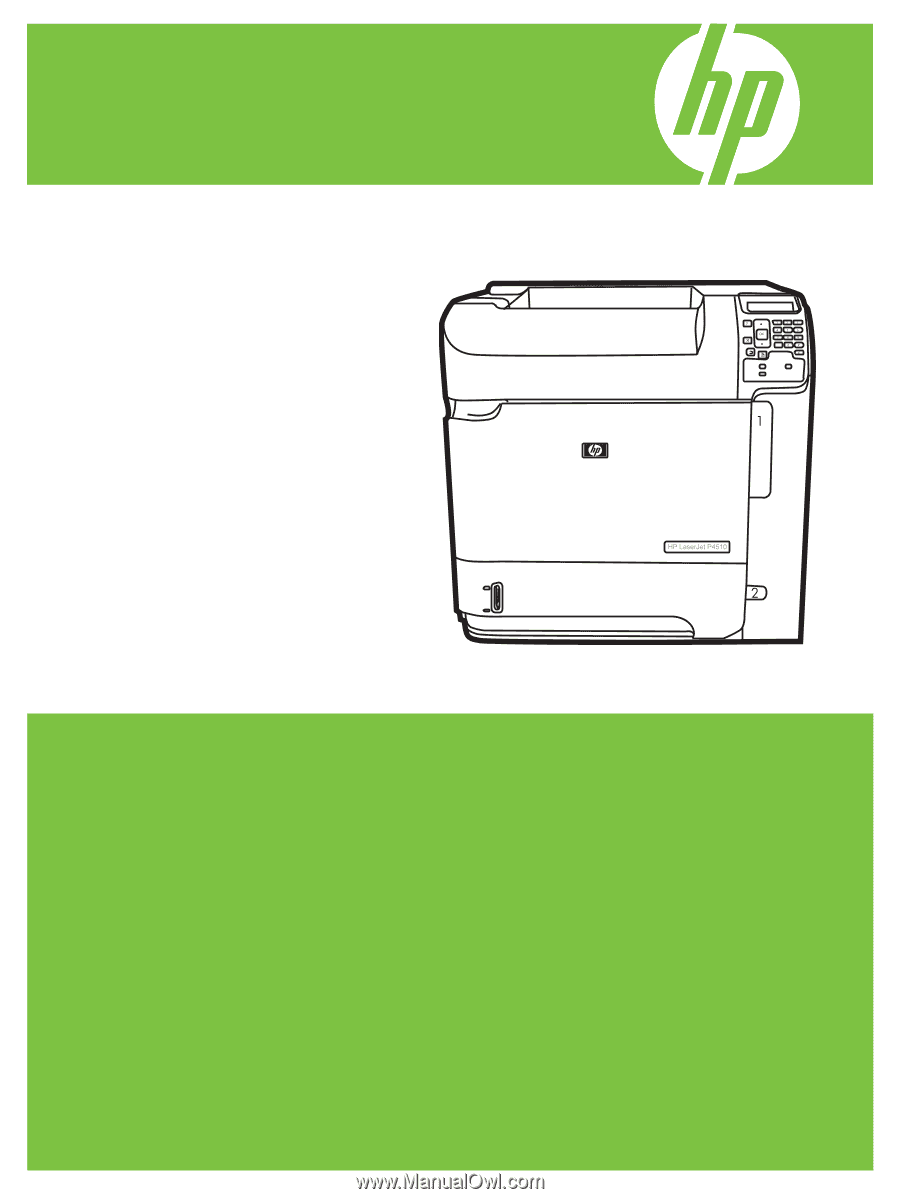
HP LaserJet P4010 and P4510 Series Printers
Service Manual