HP LaserJet P4510 Service Manual - Page 137
Fuser/delivery block, Paper trays, Printing from Tray 1, Formatter system
 |
View all HP LaserJet P4510 manuals
Add to My Manuals
Save this manual to your list of manuals |
Page 137 highlights
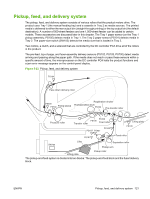
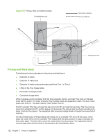
Fuser/delivery block The fuser/delivery block consists of rollers, sensors, the fuser, and the output delivery assembly. The rollers transport the media through the fuser/delivery block paper path. The fuser applies heat and pressure to the media to permanently bond the toner image to the media. The output delivery assembly sends the printed media either to the rear output bin (if the rear output door is open) or to the top output bin (the default output delivery bin). Sensors along the paper path detect media movement, jams, and the top output-bin capacity. Paper trays Printing from Tray 1 The Tray 1 paper sensor (PS105) detects the presence of media in Tray 1. When the DC controller PCA receives the print command, the product starts the initial rotation phase, which consists of feed motor warm-up, scanner motor warm-up, high-voltage control sequence, and fuser warm-up. When the initial rotation phase ends, the Tray 1 pickup solenoid (SL102) is activated. The cam rotates, the paper-tray lifter rises, and the media comes in contact with the Tray 1 pickup roller. At the same time, the Tray 1 pickup roller rotates twice and picks up a sheet of media from Tray 1. The separation pad prevents additional sheets from feeding with the first sheet. The sheet then reaches the registration assembly, where its skew is corrected. The sheet then passes through the transfer, separation, and fusing stages; through the delivery unit; and is to the output bin. NOTE: If media is removed from Tray 1 after the initial rotation phase, but before the pickup roller pulls the media from the tray, the Tray 1 pickup roller might continue to rotate up to six times, after which a jam detected. Printing from Tray 2 When the DC controller PCA receives the print command, the feed motor (M101) and scanner motor start their rotation. When the feed motor reaches its prescribed speed, the feed roller clutch (CL101) and Tray 2 pickup solenoid (SL101) are activated. (The feed motor rotation drives the Tray 2 pickup roller, Tray 2 feed roller, Tray 2 separation roller, and paper-feed rollers.) The Tray 2 pickup roller, which the pickup solenoid activates, rotates once and picks up the media in the tray. The separation roller prevents additional sheets from feeding with the first sheet, and the media is fed to the pre-feed sensor (PS102). The sheet then reaches the registration assembly, where its skew is corrected. The sheet then passes through the transfer, separation, and fusing stages; through the delivery unit; and to the output bin. Formatter system The formatter is involved in the following procedures. ● Controlling the Sleep mode ● Receiving and processing print data from the various product inputs ● Monitoring control-panel functions and relaying product status information (through the control panel and the bidirectional input/output) ● Developing and coordinating data placement and timing with the DC controller PCA ENWW Pickup, feed, and delivery system 123
-
 1
1 -
2
-
3
-
4
-
5
-
6
-
7
-
8
-
9
-
10
-
11
-
12
-
13
-
14
-
15
-
16
-
17
-
18
-
19
-
20
-
21
-
22
-
23
-
24
-
25
-
26
-
27
-
28
-
29
-
30
-
31
-
32
-
33
-
34
-
35
-
36
-
37
-
38
-
39
-
40
-
41
-
42
-
43
-
44
-
45
-
46
-
47
-
48
-
49
-
50
-
51
-
52
-
53
-
54
-
55
-
56
-
57
-
58
-
59
-
60
-
61
-
62
-
63
-
64
-
65
-
66
-
67
-
68
-
69
-
70
-
71
-
72
-
73
-
74
-
75
-
76
-
77
-
78
-
79
-
80
-
81
-
82
-
83
-
84
-
85
-
86
-
87
-
88
-
89
-
90
-
91
-
92
-
93
-
94
-
95
-
96
-
97
-
98
-
99
-
100
-
101
-
102
-
103
-
104
-
105
-
106
-
107
-
108
-
109
-
110
-
111
-
112
-
113
-
114
-
115
-
116
-
117
-
118
-
119
-
120
-
121
-
122
-
123
-
124
-
125
-
126
-
127
-
128
-
129
-
130
-
131
-
 132
132 -
 133
133 -
 134
134 -
 135
135 -
 136
136 -
 137
137 -
 138
138 -
 139
139 -
 140
140 -
 141
141 -
 142
142 -
143
-
144
-
145
-
146
-
147
-
148
-
149
-
150
-
151
-
152
-
153
-
154
-
155
-
156
-
157
-
158
-
159
-
160
-
161
-
162
-
163
-
164
-
165
-
166
-
167
-
168
-
169
-
170
-
171
-
172
-
173
-
174
-
175
-
176
-
177
-
178
-
179
-
180
-
181
-
182
-
183
-
184
-
185
-
186
-
187
-
188
-
189
-
190
-
191
-
192
-
193
-
194
-
195
-
196
-
197
-
198
-
199
-
200
-
201
-
202
-
203
-
204
-
205
-
206
-
207
-
208
-
209
-
210
-
211
-
212
-
213
-
214
-
215
-
216
-
217
-
218
-
219
-
220
-
221
-
222
-
223
-
224
-
225
-
226
-
227
-
228
-
229
-
230
-
231
-
232
-
233
-
234
-
235
-
236
-
237
-
238
-
239
-
240
-
241
-
242
-
243
-
244
-
245
-
246
-
247
-
248
-
249
-
250
-
251
-
252
-
253
-
254
-
255
-
256
-
257
-
258
-
259
-
260
-
261
-
262
-
263
-
264
-
265
-
266
-
267
-
268
-
269
-
270
-
271
-
272
-
273
-
274
-
275
-
276
-
277
-
278
-
279
-
280
-
281
-
282
-
283
-
284
-
285
-
286
-
287
-
288
-
289
-
290
-
291
-
292
-
293
-
294
-
295
-
296
-
297
-
298
-
299
-
300
-
301
-
302
-
303
-
304
-
305
-
306
-
307
-
308
-
309
-
310
-
311
-
312
-
313
-
314
-
315
-
316
-
317
-
318
-
319
-
320
-
321
-
322
-
323
-
324
-
325
-
326
-
327
-
328
-
329
-
330
-
331
-
332
-
333
-
334
-
335
-
336
-
337
-
338
-
339
-
340
-
341
-
342
-
343
-
344
-
345
-
346
-
347
-
348
-
349
-
350
-
351
-
352
-
353
-
354
-
355
-
356
-
357
-
358
-
359
-
360
-
361
-
362
-
363
-
364
-
365
-
366
-
367
-
368
-
369
-
370
-
371
-
372
-
373
-
374
-
375
-
376
-
377
-
378
-
379
-
380
-
381
-
382
-
383
-
384
-
385
-
386
-
387
-
388
-
389
-
390
-
391
-
392
-
393
-
394
-
395
-
396
-
397
-
398
-
399
-
400
-
401
-
402
-
403
-
404
-
405
-
406
-
407
-
408
-
409
-
410
-
411
-
412
-
413
-
414
-
415
-
416
-
417
-
418
-
419
-
420
-
421
-
422
-
423
-
424
-
425
-
426
-
427
-
428
-
429
-
430
-
431
-
432
-
433
-
434
-
435
-
436
-
437
-
438
-
439
-
440
-
441
-
442
-
443
-
444
-
445
-
446
-
447
-
448
-
449
-
450
-
451
-
452
-
453
-
454
-
455
-
456
-
457
-
458
-
459
-
460
-
461
-
462
-
463
-
464
-
465
-
466
-
467
-
468
-
469
-
470
-
471
-
472
-
473
-
474
-
475
-
476
-
477
-
478
-
479
-
480
-
481
-
482
-
483
-
484
-
485
-
486
-
487
-
488
-
489
-
490
-
491
-
492
-
493
-
494
-
495
-
496
-
497
-
498
-
499
-
500
-
501
-
502
-
503
-
504
-
505
-
506
-
507
-
508
-
509
-
510
-
511
-
512
-
513
-
514
-
515
-
516
-
517
-
518
-
519
-
520
-
521
-
522
-
523
-
524
-
525
-
526
-
527
-
528
-
529
-
530
-
531
-
532
 |
 |