HP Mellanox SX1018 Mellanox MLNX-OS User Manual for SX1018HP Ethernet Managed - Page 62
Vlans
 |
View all HP Mellanox SX1018 manuals
Add to My Manuals
Save this manual to your list of manuals |
Page 62 highlights
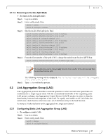
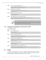
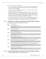
Step 3. Step 4. Step 5. Step 6. Create a port-channel entity. Run: switch (config) # interface port-channel 1 switch (config interface port-channel 1) # Change back to config mode. switch (config interface port-channel 1) # exit switch (config) # Enable LACP in the switch. Run: switch (config) # lacp switch (config) # Add a physical port to the port-channel. Run: switch (config interface ethernet 1/4) # channel-group 1 mode on switch (config interface ethernet 1/4) # Rev 1.6.2 If the physical port is operationally up, this port will be an active member of the aggregation. Consequently, it will be able to convey traffic. 5.2.2 Configuring Link Aggregation Control Protocol (LACP) To configure LACP: Step 1. Log in as admin. Step 2. Enter config mode. Run: switch > enable switch # configure terminal Step 3. Create a port-channel entity. Run: switch (config) # interface port-channel 1 switch (config interface port-channel 1) # Step 4. Change back to config mode. Run: switch (config interface port-channel 1) # exit switch (config) # Step 5. Enable LACP in the switch. Run: switch (config) # lacp switch (config) # Step 6. Add a physical port to the port-channel. Run: switch (config interface ethernet 1/4) # channel-group 1 mode active/passive switch (config interface ethernet 1/4) # 5.3 VLANs A Virtual Local Area Network (VLAN) is an L2 segment of the network which defines a broadcast domain and is identified by a tag added to all Ethernet frames running within the domain. This tag is called a VLAN ID (VID) and can take a value of 1-4094. Mellanox Technologies 62
-
 1
1 -
2
-
3
-
4
-
5
-
6
-
7
-
8
-
9
-
10
-
11
-
12
-
13
-
14
-
15
-
16
-
17
-
18
-
19
-
20
-
21
-
22
-
23
-
24
-
25
-
26
-
27
-
28
-
29
-
30
-
31
-
32
-
33
-
34
-
35
-
36
-
37
-
38
-
39
-
40
-
41
-
42
-
43
-
44
-
45
-
46
-
47
-
48
-
49
-
50
-
51
-
52
-
53
-
54
-
55
-
56
-
 57
57 -
 58
58 -
 59
59 -
 60
60 -
 61
61 -
 62
62 -
 63
63 -
 64
64 -
 65
65 -
 66
66 -
 67
67 -
68
-
69
-
70
-
71
-
72
-
73
-
74
-
75
-
76
-
77
 |
 |