HP Model 712/100 hp 9000 series 700 model 712 service handbook (a2615-90039) - Page 115
Remove the Fan/LED assembly.
 |
View all HP Model 712/100 manuals
Add to My Manuals
Save this manual to your list of manuals |
Page 115 highlights
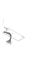
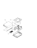
4. Remove the Fan/LED assembly. Squeeze the clip on the side of the Fan/LED assembly cable connector to disconnect it from the power supply. From the front of the unit, push in the LED until it disengages from the chassis. Tilt the top of the fan toward the front of the unit until it disengages from the mounting pins, then remove the Fan/LED assembly, as shown in Figure 5-26. NOTICE: When replacing the fan, make sure that the arrow on its side points toward the rear of the unit. Figure 6-26. Removing the Fan/LED Assembly (C2963/64A Disk) 5. Remove the power button. Pull the power button straight off the end of the plunger. Field Replaceable Units 5-39
-
 1
1 -
2
-
3
-
4
-
5
-
6
-
7
-
8
-
9
-
10
-
11
-
12
-
13
-
14
-
15
-
16
-
17
-
18
-
19
-
20
-
21
-
22
-
23
-
24
-
25
-
26
-
27
-
28
-
29
-
30
-
31
-
32
-
33
-
34
-
35
-
36
-
37
-
38
-
39
-
40
-
41
-
42
-
43
-
44
-
45
-
46
-
47
-
48
-
49
-
50
-
51
-
52
-
53
-
54
-
55
-
56
-
57
-
58
-
59
-
60
-
61
-
62
-
63
-
64
-
65
-
66
-
67
-
68
-
69
-
70
-
71
-
72
-
73
-
74
-
75
-
76
-
77
-
78
-
79
-
80
-
81
-
82
-
83
-
84
-
85
-
86
-
87
-
88
-
89
-
90
-
91
-
92
-
93
-
94
-
95
-
96
-
97
-
98
-
99
-
100
-
101
-
102
-
103
-
104
-
105
-
106
-
107
-
108
-
109
-
 110
110 -
 111
111 -
 112
112 -
 113
113 -
 114
114 -
 115
115 -
 116
116 -
 117
117 -
 118
118 -
 119
119 -
 120
120 -
121
-
122
-
123
-
124
-
125
-
126
-
127
-
128
-
129
-
130
-
131
-
132
-
133
-
134
-
135
-
136
-
137
-
138
-
139
 |
 |

Field Replaceable Units
5–39
4.
Remove the Fan/LED assembly.
Squeeze the clip on the side of the Fan/LED assembly cable connector to discon-
nect it from the power supply.
From the front of the unit, push in
the LED until it disengages from the chassis.
Tilt the top of the fan toward the front of the unit until it disengages from the
mounting pins, then remove the Fan/LED assembly, as shown in Figure 5–26.
NOTICE:
When replacing the fan, make sure that the arrow on
its side points toward the rear of the unit.
Figure 6–26.
Removing the Fan/LED Assembly (C2963/64A Disk)
5.
Remove the power button.
Pull the power button straight off the end of the plunger.