HP Model 712/100 hp 9000 series 700 model 712 service handbook (a2615-90039) - Page 66
Determining the Faulty SIMM, Memory Size MB, Address Range
 |
View all HP Model 712/100 manuals
Add to My Manuals
Save this manual to your list of manuals |
Page 66 highlights
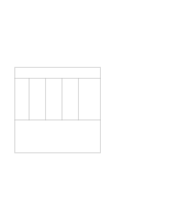
Determining the Faulty SIMM The System Responder Address is stated as if the memory is contiguous. This procedure assumes the following: D memory boards are installed in pairs of the same memory capacity D memory boards are installed first in Pair 0 (Slots 0 and 1) D there are no empty slots between memory boards To determine the faulty SIMM, perform the following steps. 1. Using Table 4-3, determine the HEX value address range for each SIMM pair in the system. Table 4-3. Memory Address Ranges Memory Size (MB) 1 MB 2 MB 4 MB 8 MB 16 MB 32 MB 64 MB 128 MB 192 MB Address Range 0x00000000 - 0x000FFFFF 0x00000000 - 0x001FFFFF 0x00000000 - 0x003FFFFF 0x00000000 - 0x007FFFFF 0x00000000 - 0x00FFFFFF 0x00000000 - 0x01FFFFFF 0x00000000 - 0x03FFFFFF 0x00000000 - 0x07FFFFFF 0x00000000 - 0x13FFFFFF For example, if the system configuration is: Pair 1: Pair 0: 16 MB SIMMs = 32 MB total for pair = 0x01FFFFFF 8 MB SIMMs = 16 MB total for pair = 0x00FFFFFF The SIMM address ranges are: Pair 1: Pair 0: Addresses 0x00000000 - 0x01FFFFFF Addresses 0x02000000 - 0x02FFFFFF Troubleshooting 4-7
-
 1
1 -
2
-
3
-
4
-
5
-
6
-
7
-
8
-
9
-
10
-
11
-
12
-
13
-
14
-
15
-
16
-
17
-
18
-
19
-
20
-
21
-
22
-
23
-
24
-
25
-
26
-
27
-
28
-
29
-
30
-
31
-
32
-
33
-
34
-
35
-
36
-
37
-
38
-
39
-
40
-
41
-
42
-
43
-
44
-
45
-
46
-
47
-
48
-
49
-
50
-
51
-
52
-
53
-
54
-
55
-
56
-
57
-
58
-
59
-
60
-
 61
61 -
 62
62 -
 63
63 -
 64
64 -
 65
65 -
 66
66 -
 67
67 -
 68
68 -
 69
69 -
 70
70 -
 71
71 -
72
-
73
-
74
-
75
-
76
-
77
-
78
-
79
-
80
-
81
-
82
-
83
-
84
-
85
-
86
-
87
-
88
-
89
-
90
-
91
-
92
-
93
-
94
-
95
-
96
-
97
-
98
-
99
-
100
-
101
-
102
-
103
-
104
-
105
-
106
-
107
-
108
-
109
-
110
-
111
-
112
-
113
-
114
-
115
-
116
-
117
-
118
-
119
-
120
-
121
-
122
-
123
-
124
-
125
-
126
-
127
-
128
-
129
-
130
-
131
-
132
-
133
-
134
-
135
-
136
-
137
-
138
-
139
 |
 |
