HP Model 712/100 hp 9000 series 700 model 712 service handbook (a2615-90039) - Page 45
removed, in place
 |
View all HP Model 712/100 manuals
Add to My Manuals
Save this manual to your list of manuals |
Page 45 highlights
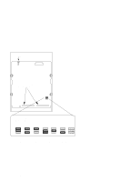
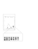
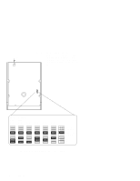
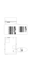
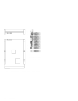
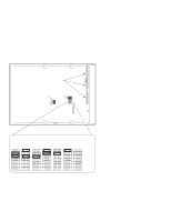
LED Front View 1 - Write Protect 2 - Unit Attention 3 - SDTR 4 - Parity Enable 5 - Auto Spin-Up 6 - Sync Spindle 7 - Sync Spindle SCSI ID 1 2 3 4 5 6 7 8 9 10 First Drive 6 Second Drive 5 4 SCSI ID 1 2 3 4 5 6 7 8 9 10 2 1 0 3 Front NOTICE: The last three jumpers (8, 9, and 10) are the SCSI ID jumpers. Jumpers 1, 2, and 7 should be removed, and jumpers 3, 4, 5, and 6 should be in place. Bottom View Terminator Power Figure 3-4. Hewlett-Packard 1-GB Winchester Drive Jumpers Configuration 3-5
-
 1
1 -
2
-
3
-
4
-
5
-
6
-
7
-
8
-
9
-
10
-
11
-
12
-
13
-
14
-
15
-
16
-
17
-
18
-
19
-
20
-
21
-
22
-
23
-
24
-
25
-
26
-
27
-
28
-
29
-
30
-
31
-
32
-
33
-
34
-
35
-
36
-
37
-
38
-
39
-
 40
40 -
 41
41 -
 42
42 -
 43
43 -
 44
44 -
 45
45 -
 46
46 -
 47
47 -
 48
48 -
 49
49 -
 50
50 -
51
-
52
-
53
-
54
-
55
-
56
-
57
-
58
-
59
-
60
-
61
-
62
-
63
-
64
-
65
-
66
-
67
-
68
-
69
-
70
-
71
-
72
-
73
-
74
-
75
-
76
-
77
-
78
-
79
-
80
-
81
-
82
-
83
-
84
-
85
-
86
-
87
-
88
-
89
-
90
-
91
-
92
-
93
-
94
-
95
-
96
-
97
-
98
-
99
-
100
-
101
-
102
-
103
-
104
-
105
-
106
-
107
-
108
-
109
-
110
-
111
-
112
-
113
-
114
-
115
-
116
-
117
-
118
-
119
-
120
-
121
-
122
-
123
-
124
-
125
-
126
-
127
-
128
-
129
-
130
-
131
-
132
-
133
-
134
-
135
-
136
-
137
-
138
-
139
 |
 |

Configuration
3–5
1 — Write Protect
2 — Unit Attention
3 — SDTR
4 — Parity Enable
5 — Auto Spin–Up
6 — Sync Spindle
7 — Sync Spindle
1
2
3
4
5
Front View
LED
Bottom View
Front
8
9
10
6
7
SCSI
ID
NOTICE:
The last three jumpers
(8, 9, and 10)
are the
SCSI
ID
jumpers.
Jumpers
1, 2,
and
7
should
be
removed
,
and jumpers
3, 4, 5,
and
6
should be
in place
.
First
Drive
Second
Drive
Terminator
Power
6
5
4
3
2
1
0
SCSI
ID
1
2
3
4
5
8
9
10
6
7
Figure 3–4.
Hewlett–Packard 1–GB Winchester Drive Jumpers