HP Model 712/100 hp 9000 series 700 model 712 service handbook (a2615-90039) - Page 22
System Unit Front Panel Controls and LEDs
 |
View all HP Model 712/100 manuals
Add to My Manuals
Save this manual to your list of manuals |
Page 22 highlights
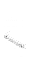
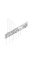
- Serial Interface and X.25 board Serial interface is logically identical to the workstation's built-in serial interface X.25 supports 1.2 to 19.2kps X.25 supports implementation of the LAP-B data-link protocol Two-headed external cable allows simultaneous use of both functions - Graphics card Supports additional monitor, same type as system unit's D Optional I/O (supported by single TeleShare slot) - TeleShare board: integrates the telephone into the workstation environment System Unit Front Panel Controls and LEDs Before powering on the system, you should become familiar with the system unit controls. Figure 1-1 shows the locations of the system unit front panel controls and LEDs. System Power LED System Power Switch Floppy Drive Activity LED (optional) Floppy Drive Eject Button (optional) Figure 1-1. System Unit Front Panel Controls and LEDs Product Information 1-3
-
 1
1 -
2
-
3
-
4
-
5
-
6
-
7
-
8
-
9
-
10
-
11
-
12
-
13
-
14
-
15
-
16
-
 17
17 -
 18
18 -
 19
19 -
 20
20 -
 21
21 -
 22
22 -
 23
23 -
 24
24 -
 25
25 -
 26
26 -
 27
27 -
28
-
29
-
30
-
31
-
32
-
33
-
34
-
35
-
36
-
37
-
38
-
39
-
40
-
41
-
42
-
43
-
44
-
45
-
46
-
47
-
48
-
49
-
50
-
51
-
52
-
53
-
54
-
55
-
56
-
57
-
58
-
59
-
60
-
61
-
62
-
63
-
64
-
65
-
66
-
67
-
68
-
69
-
70
-
71
-
72
-
73
-
74
-
75
-
76
-
77
-
78
-
79
-
80
-
81
-
82
-
83
-
84
-
85
-
86
-
87
-
88
-
89
-
90
-
91
-
92
-
93
-
94
-
95
-
96
-
97
-
98
-
99
-
100
-
101
-
102
-
103
-
104
-
105
-
106
-
107
-
108
-
109
-
110
-
111
-
112
-
113
-
114
-
115
-
116
-
117
-
118
-
119
-
120
-
121
-
122
-
123
-
124
-
125
-
126
-
127
-
128
-
129
-
130
-
131
-
132
-
133
-
134
-
135
-
136
-
137
-
138
-
139
 |
 |
