IBM x3400 User Guide - Page 33
System-board, switches - bios update
 |
View all IBM x3400 manuals
Add to My Manuals
Save this manual to your list of manuals |
Page 33 highlights
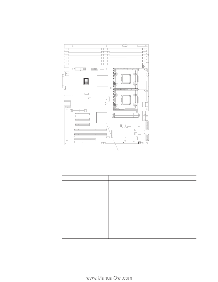
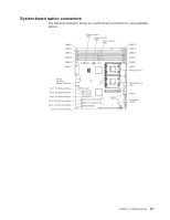
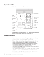
System-board switches The following illustration shows the SW4 switch (Boot block/Clear CMOS) on the system board. DIMM LEDs 6 12 5 11 4 10 39 28 17 SW4 (Boot block/Clear CMOS) The following table describes the function of each pin on the SW4 switch (Boot block/Clear CMOS) on the system board. Table 3. System board SW4 switch Switch pin number 1 Description Boot block: v When this switch is on 1, this is normal mode. v When this switch is toggled to On, this enables the system to recover if the BIOS code becomes damaged. See the Problem Determination and Service Guide for information about recovering from a BIOS update failure. 2 Clear CMOS: v When this switch is on 2, this is normal mode. This keeps the CMOS data. v When this switch is toggled to On, this clears the CMOS data, which clears the power-on password and administrator password. Chapter 2. Installing options 19
-
 1
1 -
2
-
3
-
4
-
5
-
6
-
7
-
8
-
9
-
10
-
11
-
12
-
13
-
14
-
15
-
16
-
17
-
18
-
19
-
20
-
21
-
22
-
23
-
24
-
25
-
26
-
27
-
 28
28 -
 29
29 -
 30
30 -
 31
31 -
 32
32 -
 33
33 -
 34
34 -
 35
35 -
 36
36 -
 37
37 -
 38
38 -
39
-
40
-
41
-
42
-
43
-
44
-
45
-
46
-
47
-
48
-
49
-
50
-
51
-
52
-
53
-
54
-
55
-
56
-
57
-
58
-
59
-
60
-
61
-
62
-
63
-
64
-
65
-
66
-
67
-
68
-
69
-
70
-
71
-
72
-
73
-
74
-
75
-
76
-
77
-
78
-
79
-
80
-
81
-
82
-
83
-
84
-
85
-
86
-
87
-
88
-
89
-
90
-
91
-
92
-
93
-
94
-
95
-
96
-
97
-
98
-
99
-
100
-
101
-
102
-
103
-
104
-
105
-
106
-
107
-
108
-
109
-
110
-
111
-
112
-
113
-
114
-
115
-
116
-
117
-
118
-
119
-
120
-
121
-
122
-
123
-
124
-
125
-
126
-
127
-
128
-
129
-
130
-
131
-
132
-
133
-
134
 |
 |