IBM x3400 User Guide - Page 60
Installing, adapter
 |
View all IBM x3400 manuals
Add to My Manuals
Save this manual to your list of manuals |
Page 60 highlights
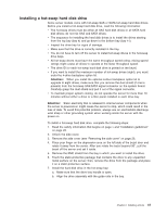
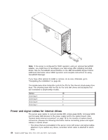
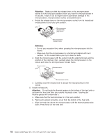
Note: When you install the optional 4-drive backplane option kit to upgrade to eight drives, make sure that you remove the dust shield (if one is present) from the hot-swap SAS/SATA signal connector on the system board. Carefully grasp the dust shield and pull it out of the signal connector. For more information about the requirements for SAS cables and connecting SAS devices, see the documentation that comes with these devices. For a list of supported options for the server, see http://www.ibm.com/servers/ eserver/serverproven/compat/us/. Installing an adapter The following notes describe the types of adapters that the server supports and other information that you must consider when installing an adapter. Adapter that the server supports might vary, depending on your server model. v Locate the documentation that comes with the adapter and follow those instructions in addition to the instructions in this section. If you must change the switch setting or jumper settings on the adapter, follow the instructions that come with the adapter. v Read the documentation that comes with your operating system. v The server comes with the following adapter connectors, or slots: - Slot 1, PCI Express x8 (x4) Important: The x8 (x4) designation for slot 1 identifies an x8 slot that is designed to support x4 adapters and x8 adapters that can downshift to operate at the x4 bandwidth. If you install an x8 adapter in slot 1 that can downshift to the x4 bandwidth, it will run at the x4 bandwidth. The x8 connector can be used for x4 and x8 adapters. Check the information that comes with your adapter for compatibility information. - Slot 2, PCI Express x8 (x8) - Slot 3, PCI Express x8 (x8) - Slot 4, PCI-X 64-bit/133 MHz - Slot 5, PCI-X 64-bit/133 MHz - Slot 6, PCI 32-bit/33 MHz v You can install full-length adapters that are included in the ServerProven® list in slots 2, 3, 4 and 5. You can only install half-length adapters in slots 1 and 6. v The 32-bit slot 6 supports 5.0 V keyed PCI adapters; they do not support 3.3 V keyed adapters. Universal adapters are supported in slots 4 and 5 if they are universally keyed. v You can order an optional IBM ServeRAID-MR10is VAULT SAS/SATA Controller that supports RAID levels 0, 1, 5, 6, 10, 50, and 60. You can install the ServeRAID-MR10is SAS/SATA controller only in server models with eight 3.5 inch hot-swap hard disk drives installed. PCI slot 2 is the dedicated slot for the ServeRAID-MR10is SAS/SATA controller. For instructions on how to install the ServeRAID-MR10is SAS/SATA controller, see "Installing the optional IBM ServeRAID-MR10is VAULT SAS/SATA Controller" on page 60. Note: Note: The onboard RAID controller will be disabled by BIOS when the ServeRAID-MR10is SAS/SATA controller is installed in the server. v The server scans PCI Express slot 1, PCI-X slots 4 and 5, and PCI-Express slots 2 and 3 to assign system resources. Then, the server starts the devices in the 46 System x3400 Types 7973, 7974, 7975, and 7976: User's Guide
-
 1
1 -
2
-
3
-
4
-
5
-
6
-
7
-
8
-
9
-
10
-
11
-
12
-
13
-
14
-
15
-
16
-
17
-
18
-
19
-
20
-
21
-
22
-
23
-
24
-
25
-
26
-
27
-
28
-
29
-
30
-
31
-
32
-
33
-
34
-
35
-
36
-
37
-
38
-
39
-
40
-
41
-
42
-
43
-
44
-
45
-
46
-
47
-
48
-
49
-
50
-
51
-
52
-
53
-
54
-
 55
55 -
 56
56 -
 57
57 -
 58
58 -
 59
59 -
 60
60 -
 61
61 -
 62
62 -
 63
63 -
 64
64 -
 65
65 -
66
-
67
-
68
-
69
-
70
-
71
-
72
-
73
-
74
-
75
-
76
-
77
-
78
-
79
-
80
-
81
-
82
-
83
-
84
-
85
-
86
-
87
-
88
-
89
-
90
-
91
-
92
-
93
-
94
-
95
-
96
-
97
-
98
-
99
-
100
-
101
-
102
-
103
-
104
-
105
-
106
-
107
-
108
-
109
-
110
-
111
-
112
-
113
-
114
-
115
-
116
-
117
-
118
-
119
-
120
-
121
-
122
-
123
-
124
-
125
-
126
-
127
-
128
-
129
-
130
-
131
-
132
-
133
-
134
 |
 |