IBM x3400 User Guide - Page 57
Installing, simple-swap, drive
 |
View all IBM x3400 manuals
Add to My Manuals
Save this manual to your list of manuals |
Page 57 highlights
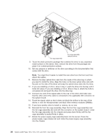
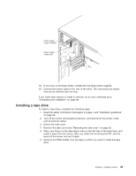
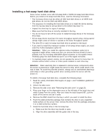
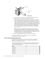
Device ID Drive bay 10 6 Drive bay 11 7 Installing a simple-swap SATA hard disk drive Some server models come with simple-swap SATA hard disk drives that are accessible from the front of the server. You must turn off the server before installing simple-swap drives in the server. Before you install a simple-swap SATA hard disk drive, read the following information: v You can only install four simple-swap SATA hard disk drives in the server. v The sequence for installing the hard disk drives is to install the drives starting from the bottom bay (bay 7) and go up to the top bay (bay 4). To install a simple-swap hard disk drive, complete the following steps: 1. Read the safety information that begins on page v and "Installation guidelines" on page 22. 2. Turn off the server and peripheral devices and disconnect all external cables and power cords. 3. Unlock the side cover. 4. Remove the side cover (see "Removing the side cover" on page 26. 5. Place your finger on the depression area on the left side of the bezel door and rotate it away from the server. After you rotate the bezel beyond 90°, pull the bezel off the server and set it aside. 6. Touch the static-protective package that contains the drive to any unpainted metal surface on the server; then, remove the drive from the package and place it on a static-protective surface. 7. Align the drive assembly with the guide rails in the bay (the connector end of the drive goes in first). 8. Press the drive assembly loops toward each other; then, carefully slide the drive assembly into the drive bay until it stops and release the loops. Note: Do not release the loops on the drive assembly until it is completely seated. Chapter 2. Installing options 43
-
 1
1 -
2
-
3
-
4
-
5
-
6
-
7
-
8
-
9
-
10
-
11
-
12
-
13
-
14
-
15
-
16
-
17
-
18
-
19
-
20
-
21
-
22
-
23
-
24
-
25
-
26
-
27
-
28
-
29
-
30
-
31
-
32
-
33
-
34
-
35
-
36
-
37
-
38
-
39
-
40
-
41
-
42
-
43
-
44
-
45
-
46
-
47
-
48
-
49
-
50
-
51
-
 52
52 -
 53
53 -
 54
54 -
 55
55 -
 56
56 -
 57
57 -
 58
58 -
 59
59 -
 60
60 -
 61
61 -
 62
62 -
63
-
64
-
65
-
66
-
67
-
68
-
69
-
70
-
71
-
72
-
73
-
74
-
75
-
76
-
77
-
78
-
79
-
80
-
81
-
82
-
83
-
84
-
85
-
86
-
87
-
88
-
89
-
90
-
91
-
92
-
93
-
94
-
95
-
96
-
97
-
98
-
99
-
100
-
101
-
102
-
103
-
104
-
105
-
106
-
107
-
108
-
109
-
110
-
111
-
112
-
113
-
114
-
115
-
116
-
117
-
118
-
119
-
120
-
121
-
122
-
123
-
124
-
125
-
126
-
127
-
128
-
129
-
130
-
131
-
132
-
133
-
134
 |
 |