IBM x3400 User Guide - Page 52
microprocessor
 |
View all IBM x3400 manuals
Add to My Manuals
Save this manual to your list of manuals |
Page 52 highlights
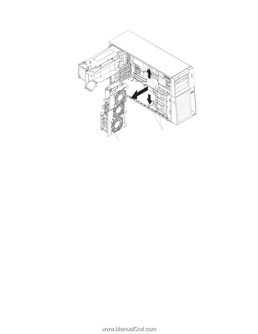
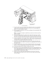
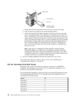
Fan cage assembly Fan cage assembly release buttons 9. Touch the static-protective package that contains the drive to any unpainted metal surface on the server; then, remove the drive from the package and place it on a static-protective surface. 10. Set any jumpers or switches on the drive according to the documentation that comes with the drive. Note: You might find it easier to install the new drive from the front and then attach the cables. 11. Remove the blue optical drive rails from the inside of the drive bay in which you want to install the drive. Align the holes on the blue optical drive rails with the pins on the side of the drive and snap the optical drive rails onto the drive. 12. If you are installing a 5.25-in. drive in bay 2, push the drive into the bay until it locks into place. If you are installing a 3.5-in. drive in bay 2, attach the 5.25-in. conversion kit and push the drive into the drive bay. 13. Connect one end of the signal cable to the rear of the drive and make sure that the other end of the cable is connected to the applicable IDE connector on the system board. 14. Route the signal cable so that it does not block the airflow to the rear of the drives or over the microprocessor and dual inline memory modules (DIMMs). 15. If you have another drive to install or remove, do so now. 16. Reinstall the front fan cage assembly. Align the front fan cage assembly over the fan cage assembly slot and with the connector on the system board. Lower the fan cage assembly into the chassis and press down firmly until the fan cage assembly is seated firmly in place. 17. Rotate the power-supply cage assembly back into the server. Press the power-supply cage release tab and rotate the power-supply cage assembly into the chassis. 38 System x3400 Types 7973, 7974, 7975, and 7976: User's Guide
-
 1
1 -
2
-
3
-
4
-
5
-
6
-
7
-
8
-
9
-
10
-
11
-
12
-
13
-
14
-
15
-
16
-
17
-
18
-
19
-
20
-
21
-
22
-
23
-
24
-
25
-
26
-
27
-
28
-
29
-
30
-
31
-
32
-
33
-
34
-
35
-
36
-
37
-
38
-
39
-
40
-
41
-
42
-
43
-
44
-
45
-
46
-
 47
47 -
 48
48 -
 49
49 -
 50
50 -
 51
51 -
 52
52 -
 53
53 -
 54
54 -
 55
55 -
 56
56 -
 57
57 -
58
-
59
-
60
-
61
-
62
-
63
-
64
-
65
-
66
-
67
-
68
-
69
-
70
-
71
-
72
-
73
-
74
-
75
-
76
-
77
-
78
-
79
-
80
-
81
-
82
-
83
-
84
-
85
-
86
-
87
-
88
-
89
-
90
-
91
-
92
-
93
-
94
-
95
-
96
-
97
-
98
-
99
-
100
-
101
-
102
-
103
-
104
-
105
-
106
-
107
-
108
-
109
-
110
-
111
-
112
-
113
-
114
-
115
-
116
-
117
-
118
-
119
-
120
-
121
-
122
-
123
-
124
-
125
-
126
-
127
-
128
-
129
-
130
-
131
-
132
-
133
-
134
 |
 |