IBM x3400 User Guide - Page 44
System, Summary - setup menu
 |
View all IBM x3400 manuals
Add to My Manuals
Save this manual to your list of manuals |
Page 44 highlights
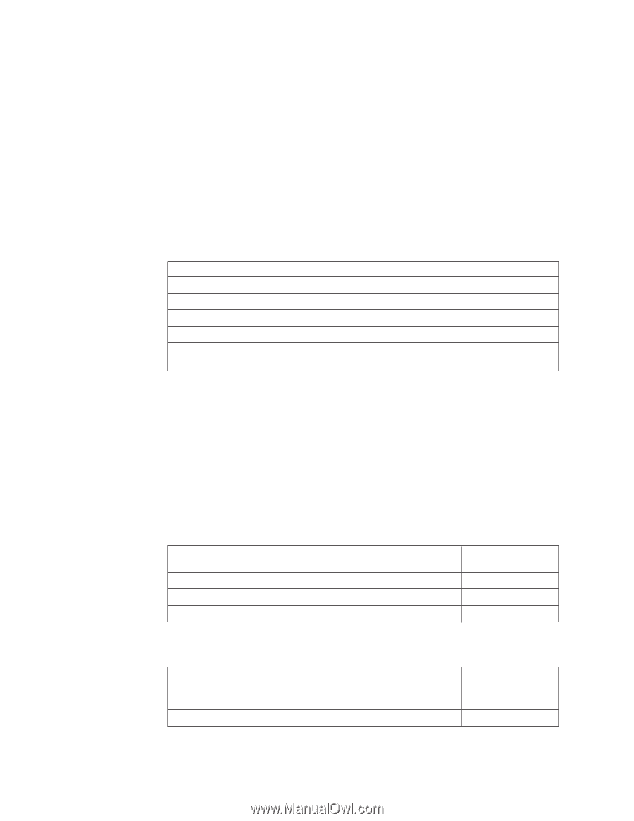
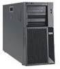
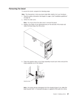
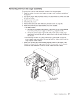
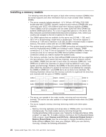
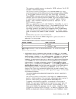
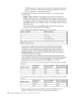
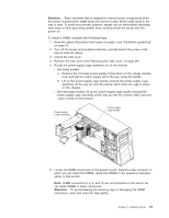
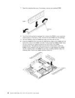
1, DIMM connector 7 (channel 2) and connector 10 (channel 3) rather than branch 0, then branch 1 will support online-sparing and branch 0 will not. - Branch 0 and branch 1 operate independently. v The following notes apply when the server operates in non-mirroring mode (normal mode): - DIMMs must be installed in matched pairs. If you install a second pair of DIMMs in DIMM connector 7 and DIMM connector 10, they do not have to be the same size, speed, type, and technology as the DIMMs in DIMM connector 1 and DIMM connector 4. However, the size, speed, type, and technology of the DIMMs that you install in DIMM connector 7 and DIMM connector 10 must match each other. - The following table shows the DIMM upgrade configuration sequence for operating in non-mirrored mode (normal mode). Table 5. DIMM upgrade configuration sequence in non-mirroring mode Number of DIMMs DIMM connectors 2 1, 4 4 1, 4, 7, 10 6 1, 4, 7, 10, 2, 5 8 1, 4, 7, 10, 2, 5, 8, 11 Note: DIMM connectors 3, 6, 9, and 12 are not functional in this server. Do not install DIMMs in these connectors. v The amount of usable memory will be reduced depending on the system configuration. A certain amount of memory must be reserved for system resources. To view the total amount of installed memory and the amount of configured memory, run the Configuration/Setup Utility program and select System Summary from the menu. For additional information, see Chapter 3, "Configuring the server," on page 75. v The following tables show examples of maximum memory capacity when the server operates in mirroring and non-mirroring modes, using identical single-rank, x8 technology or double-rank, x4 technology DIMMs. The memory capacity is dependent on the size and technology of the DIMMs that you install. Table 6. Example of the memory capacity when identical x8 technology single-rank DIMMs are used DIMMs installed x8 single-rank technology Memory available in Memory available in mirroring mode non-mirroring mode 8 512 Mb 2 GB 4 GB 8 1 Gb 4 GB 8 GB 8 2 Gb 8 GB 16 GB Table 7. Example of the memory capacity when identical x4 technology double-rank DIMMs are used DIMMs installed x4 double-rank technology Memory available in Memory available in mirroring mode non-mirroring mode 8 512 Mb 8 GB 16 GB 8 1 Gb 16 GB 32 GB v When you restart the server after adding or removing a DIMM, the server displays a message that the memory configuration has changed. 30 System x3400 Types 7973, 7974, 7975, and 7976: User's Guide
-
 1
1 -
2
-
3
-
4
-
5
-
6
-
7
-
8
-
9
-
10
-
11
-
12
-
13
-
14
-
15
-
16
-
17
-
18
-
19
-
20
-
21
-
22
-
23
-
24
-
25
-
26
-
27
-
28
-
29
-
30
-
31
-
32
-
33
-
34
-
35
-
36
-
37
-
38
-
 39
39 -
 40
40 -
 41
41 -
 42
42 -
 43
43 -
 44
44 -
 45
45 -
 46
46 -
 47
47 -
 48
48 -
 49
49 -
50
-
51
-
52
-
53
-
54
-
55
-
56
-
57
-
58
-
59
-
60
-
61
-
62
-
63
-
64
-
65
-
66
-
67
-
68
-
69
-
70
-
71
-
72
-
73
-
74
-
75
-
76
-
77
-
78
-
79
-
80
-
81
-
82
-
83
-
84
-
85
-
86
-
87
-
88
-
89
-
90
-
91
-
92
-
93
-
94
-
95
-
96
-
97
-
98
-
99
-
100
-
101
-
102
-
103
-
104
-
105
-
106
-
107
-
108
-
109
-
110
-
111
-
112
-
113
-
114
-
115
-
116
-
117
-
118
-
119
-
120
-
121
-
122
-
123
-
124
-
125
-
126
-
127
-
128
-
129
-
130
-
131
-
132
-
133
-
134
 |
 |