IBM x3400 User Guide - Page 78
controller.
 |
View all IBM x3400 manuals
Add to My Manuals
Save this manual to your list of manuals |
Page 78 highlights
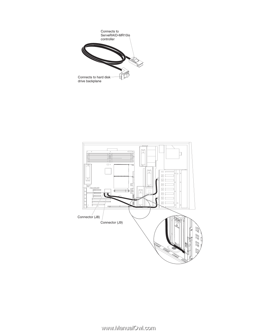
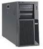
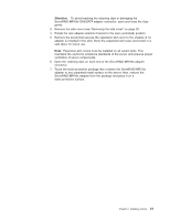
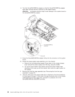
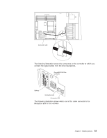
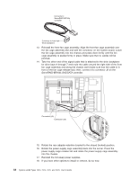
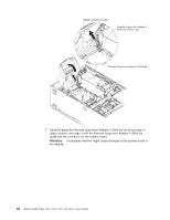
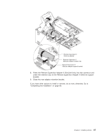
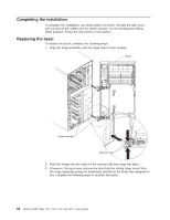
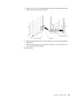
13. Reinstall the front fan cage assembly. Align the front fan cage assembly over the fan cage assembly slot and with the connector on the system board. Lower the fan cage assembly into the chassis and press down firmly until the fan cage assembly is seated firmly in place. Make sure that no cables will be pinched. 14. Take the other end of the signal cable that is attached to the drive backplane for drive bays 4 through 7 and route the cable around the right side of the front fan cage assembly and along the chassis wall (make sure that the cable is in front of the fan cage release tab): then, connect it to connector J8 on the ServeRAID-MR10is SAS/SATA controller. 15. Rotate the rear adapter-retention bracket to the closed (locked) position. 16. Rotate the power-supply cage assembly back into the server. Press the power-supply cage release tab and rotate the power-supply cage assembly into the chassis. 17. Reinstall the hot-swap power supplies. 18. If you have other options to install or remove, do so now. 64 System x3400 Types 7973, 7974, 7975, and 7976: User's Guide
-
 1
1 -
2
-
3
-
4
-
5
-
6
-
7
-
8
-
9
-
10
-
11
-
12
-
13
-
14
-
15
-
16
-
17
-
18
-
19
-
20
-
21
-
22
-
23
-
24
-
25
-
26
-
27
-
28
-
29
-
30
-
31
-
32
-
33
-
34
-
35
-
36
-
37
-
38
-
39
-
40
-
41
-
42
-
43
-
44
-
45
-
46
-
47
-
48
-
49
-
50
-
51
-
52
-
53
-
54
-
55
-
56
-
57
-
58
-
59
-
60
-
61
-
62
-
63
-
64
-
65
-
66
-
67
-
68
-
69
-
70
-
71
-
72
-
 73
73 -
 74
74 -
 75
75 -
 76
76 -
 77
77 -
 78
78 -
 79
79 -
 80
80 -
 81
81 -
 82
82 -
 83
83 -
84
-
85
-
86
-
87
-
88
-
89
-
90
-
91
-
92
-
93
-
94
-
95
-
96
-
97
-
98
-
99
-
100
-
101
-
102
-
103
-
104
-
105
-
106
-
107
-
108
-
109
-
110
-
111
-
112
-
113
-
114
-
115
-
116
-
117
-
118
-
119
-
120
-
121
-
122
-
123
-
124
-
125
-
126
-
127
-
128
-
129
-
130
-
131
-
132
-
133
-
134
 |
 |