IBM x3400 User Guide - Page 74
Installing, optional, ServeRAID-MR10is, VAULT, SAS/SATA, Controller
 |
View all IBM x3400 manuals
Add to My Manuals
Save this manual to your list of manuals |
Page 74 highlights
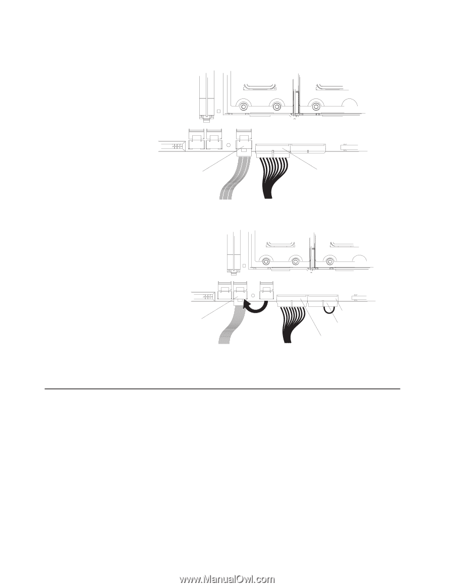
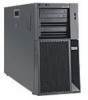
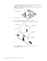
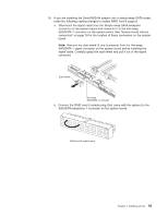
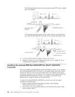
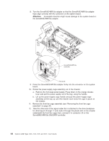
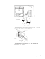
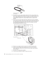
The following illustration shows how the simple-swap SATA model is cabled when it is shipped. Simple-swap SATA backplate SAS/SATA backplane 2 The following illustration shows how the cables must be connected when you install the ServeRAID-8k Controller into the simple-swap SATA model. Hot-swap SAS/SATA 1 SAS/SATA backplane 1 RAID level-5 enabler plug SAS/SATA backplane 2 11. If you have other options to install or remove, do so now. 12. Replace the side cover (see "Replacing the side cover" on page 70). Go to "Completing the installation" on page 68. Installing the optional IBM ServeRAID-MR10is VAULT SAS/SATA Controller The optional IBM ServeRAID-MR10is VAULT SAS/SATA controller can be installed only in its dedicated PCI slot 2 connector on the system board, and only in server models with eight 3.5-inch hot-swap hard disk drives. See "System-board option connectors" on page 21 for the location of the connector on the system board. The ServeRAID-MR10is SAS/SATA controller is not cabled to the system board. Instructions for routing the cables are described below. To install the ServeRAID-MR10is SAS/SATA controller and route the cables, complete the following steps: 1. Read the safety information that begins on page v and "Handling static-sensitive devices" on page 24. 2. Turn off the server and peripheral devices, and disconnect the power cords and all external cables. 60 System x3400 Types 7973, 7974, 7975, and 7976: User's Guide
-
 1
1 -
2
-
3
-
4
-
5
-
6
-
7
-
8
-
9
-
10
-
11
-
12
-
13
-
14
-
15
-
16
-
17
-
18
-
19
-
20
-
21
-
22
-
23
-
24
-
25
-
26
-
27
-
28
-
29
-
30
-
31
-
32
-
33
-
34
-
35
-
36
-
37
-
38
-
39
-
40
-
41
-
42
-
43
-
44
-
45
-
46
-
47
-
48
-
49
-
50
-
51
-
52
-
53
-
54
-
55
-
56
-
57
-
58
-
59
-
60
-
61
-
62
-
63
-
64
-
65
-
66
-
67
-
68
-
 69
69 -
 70
70 -
 71
71 -
 72
72 -
 73
73 -
 74
74 -
 75
75 -
 76
76 -
 77
77 -
 78
78 -
 79
79 -
80
-
81
-
82
-
83
-
84
-
85
-
86
-
87
-
88
-
89
-
90
-
91
-
92
-
93
-
94
-
95
-
96
-
97
-
98
-
99
-
100
-
101
-
102
-
103
-
104
-
105
-
106
-
107
-
108
-
109
-
110
-
111
-
112
-
113
-
114
-
115
-
116
-
117
-
118
-
119
-
120
-
121
-
122
-
123
-
124
-
125
-
126
-
127
-
128
-
129
-
130
-
131
-
132
-
133
-
134
 |
 |