IBM x3400 User Guide - Page 61
eserver/serverproven/compat/us/.
 |
View all IBM x3400 manuals
Add to My Manuals
Save this manual to your list of manuals |
Page 61 highlights
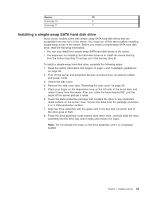
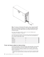
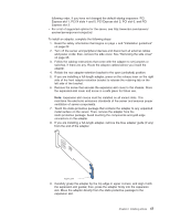
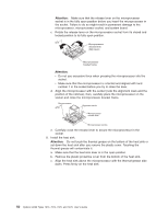
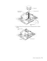
following order, if you have not changed the default startup sequence: PCI Express slot 1, PCI-X slots 4 and 5, PCI Express slot 2, PCI slot 6, and PCI Express slot 3. v For a list of supported options for the server, see http://www.ibm.com/servers/ eserver/serverproven/compat/us/. To install an adapter, complete the following steps: 1. Read the safety information that begins on page v and "Installation guidelines" on page 22. 2. Turn off the server and peripheral devices and disconnect all external cables and power cords; then, remove the side cover. See "Removing the side cover" on page 26. 3. Follow the cabling instructions that come with the adapter to set jumpers or switches, if there are any. Route the adapter cables before you install the adapter. 4. Rotate the rear adapter-retention bracket to the open (unlocked) position. 5. If you are installing a full-length adapter, press on the release lever on the right side of the front adapter-retention bracket to release the retaining tab on the left side of the bracket. 6. Remove the screw that secures the expansion-slot cover to the chassis. Store the expansion-slot cover and screw in a safe place for future use. Note: Expansion-slot covers must be installed on all vacant slots. This maintains the electronic emissions standards of the server and ensures proper ventilation of server components. 7. Touch the static-protective package that contains the adapter to any unpainted metal surface on the server. Then, remove the adapter from the static-protective package. Avoid touching the components and gold-edge connectors on the adapter. 8. If you are installing a full-length adapter, remove the blue adapter guide (if any) from the end of the adapter. Adapter guide 9. Carefully grasp the adapter by the top edge or upper corners, and align it with the expansion slot guides; then, press the adapter firmly into the expansion slot. Move the adapter directly from the static-protective package to the expansion slot. Chapter 2. Installing options 47
-
 1
1 -
2
-
3
-
4
-
5
-
6
-
7
-
8
-
9
-
10
-
11
-
12
-
13
-
14
-
15
-
16
-
17
-
18
-
19
-
20
-
21
-
22
-
23
-
24
-
25
-
26
-
27
-
28
-
29
-
30
-
31
-
32
-
33
-
34
-
35
-
36
-
37
-
38
-
39
-
40
-
41
-
42
-
43
-
44
-
45
-
46
-
47
-
48
-
49
-
50
-
51
-
52
-
53
-
54
-
55
-
 56
56 -
 57
57 -
 58
58 -
 59
59 -
 60
60 -
 61
61 -
 62
62 -
 63
63 -
 64
64 -
 65
65 -
 66
66 -
67
-
68
-
69
-
70
-
71
-
72
-
73
-
74
-
75
-
76
-
77
-
78
-
79
-
80
-
81
-
82
-
83
-
84
-
85
-
86
-
87
-
88
-
89
-
90
-
91
-
92
-
93
-
94
-
95
-
96
-
97
-
98
-
99
-
100
-
101
-
102
-
103
-
104
-
105
-
106
-
107
-
108
-
109
-
110
-
111
-
112
-
113
-
114
-
115
-
116
-
117
-
118
-
119
-
120
-
121
-
122
-
123
-
124
-
125
-
126
-
127
-
128
-
129
-
130
-
131
-
132
-
133
-
134
 |
 |