IBM x3400 User Guide - Page 77
following, illustration, shows, connectors, controller, which, connect, signal, cables, drive,
 |
View all IBM x3400 manuals
Add to My Manuals
Save this manual to your list of manuals |
Page 77 highlights
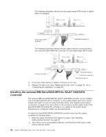
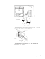
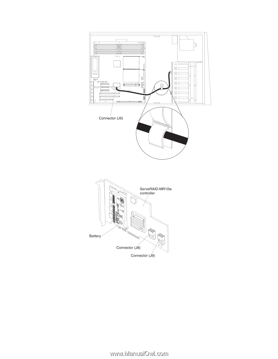
The following illustration shows the connectors on the controller to which you connect the signal cables from the drive backplanes. The following illustration shows which end of the cable connects to the backplane and to the controller. Chapter 2. Installing options 63
-
 1
1 -
2
-
3
-
4
-
5
-
6
-
7
-
8
-
9
-
10
-
11
-
12
-
13
-
14
-
15
-
16
-
17
-
18
-
19
-
20
-
21
-
22
-
23
-
24
-
25
-
26
-
27
-
28
-
29
-
30
-
31
-
32
-
33
-
34
-
35
-
36
-
37
-
38
-
39
-
40
-
41
-
42
-
43
-
44
-
45
-
46
-
47
-
48
-
49
-
50
-
51
-
52
-
53
-
54
-
55
-
56
-
57
-
58
-
59
-
60
-
61
-
62
-
63
-
64
-
65
-
66
-
67
-
68
-
69
-
70
-
71
-
 72
72 -
 73
73 -
 74
74 -
 75
75 -
 76
76 -
 77
77 -
 78
78 -
 79
79 -
 80
80 -
 81
81 -
 82
82 -
83
-
84
-
85
-
86
-
87
-
88
-
89
-
90
-
91
-
92
-
93
-
94
-
95
-
96
-
97
-
98
-
99
-
100
-
101
-
102
-
103
-
104
-
105
-
106
-
107
-
108
-
109
-
110
-
111
-
112
-
113
-
114
-
115
-
116
-
117
-
118
-
119
-
120
-
121
-
122
-
123
-
124
-
125
-
126
-
127
-
128
-
129
-
130
-
131
-
132
-
133
-
134
 |
 |
The
following
illustration
shows
the
connectors
on
the
controller
to
which
you
connect
the
signal
cables
from
the
drive
backplanes.
The
following
illustration
shows
which
end
of
the
cable
connects
to
the
backplane
and
to
the
controller.
Chapter
2.
Installing
options
63