IBM x3500 Installation Guide - Page 104
Light, diagnostics - cpu
 |
UPC - 883436005760
View all IBM x3500 manuals
Add to My Manuals
Save this manual to your list of manuals |
Page 104 highlights
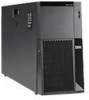
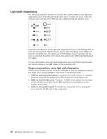
Light path diagnostics The following illustration shows the remind button and the LEDs on the light path diagnostics panel. The light path diagnostics panel is inside the server under the left-side cover, and the error LEDs are also visible through the left-side cover. 1 POWER SUPPLY 2 CONFIG TEMP REMIND MEMORY DASD/ RAID FAN CPU S_ERR VRM PCI BUS SP BUS NMI SEE INSIDE COVER FOR MORE SERVICE INFORMATION Press the remind button on the light path diagnostics panel to acknowledge that an error has occurred but indicate that you will not take immediate action. When you press the remind button, the system-error LED flashes every 2 seconds until the error is corrected. If another error occurs, the system-error LED stops flashing and is lit again. For more information about light path diagnostics, see the Problem Determination and Service Guide on the IBM System x Documentation CD. Diagnosing problems using light path diagnostics LEDs in three locations on the server are available to help you diagnose problems that might occur during installation. Use them in the following order: 1. LEDs on the front of the server: Look at the front of the server. If a system error has occurred, the system-error LED on the front of the server is lit. 2. LEDs on the left-side cover: There are 13 LEDs and a system service label on the left-side cover. Note the lit LEDs and follow the instructions on the system service label. 3. LEDs on the system board: To identify the component that is causing the error, note the lit LED next to the component. 90 IBM System x3500 Type 7977: Installation Guide
-
 1
1 -
2
-
3
-
4
-
5
-
6
-
7
-
8
-
9
-
10
-
11
-
12
-
13
-
14
-
15
-
16
-
17
-
18
-
19
-
20
-
21
-
22
-
23
-
24
-
25
-
26
-
27
-
28
-
29
-
30
-
31
-
32
-
33
-
34
-
35
-
36
-
37
-
38
-
39
-
40
-
41
-
42
-
43
-
44
-
45
-
46
-
47
-
48
-
49
-
50
-
51
-
52
-
53
-
54
-
55
-
56
-
57
-
58
-
59
-
60
-
61
-
62
-
63
-
64
-
65
-
66
-
67
-
68
-
69
-
70
-
71
-
72
-
73
-
74
-
75
-
76
-
77
-
78
-
79
-
80
-
81
-
82
-
83
-
84
-
85
-
86
-
87
-
88
-
89
-
90
-
91
-
92
-
93
-
94
-
95
-
96
-
97
-
98
-
 99
99 -
 100
100 -
 101
101 -
 102
102 -
 103
103 -
 104
104 -
 105
105 -
 106
106 -
 107
107 -
 108
108 -
 109
109 -
110
-
111
-
112
-
113
-
114
-
115
-
116
-
117
-
118
-
119
-
120
-
121
-
122
-
123
-
124
 |
 |
