IBM x3500 Installation Guide - Page 29
Number, DIMMs, connectors, Memory, Non-mirroring, mirroring
 |
UPC - 883436005760
View all IBM x3500 manuals
Add to My Manuals
Save this manual to your list of manuals |
Page 29 highlights
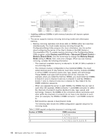
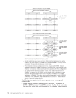
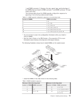
1 and DIMM connector 4. However, the size, speed, type, and technology of the DIMMs that you install in DIMM connector 7 and DIMM connector 10 must match each other. - The following table shows the DIMM upgrade configuration sequence for operating in non-mirroring mode (normal mode). Table 3. 5. DIMM upgrade configuration sequence in non-mirroring mode Number of DIMMs DIMM connectors 2 1, 4 4 1, 4, 7, 10 6 1, 4, 7, 10, 2, 5 8 1, 4, 7, 10, 2, 5, 8, 11 10 1, 4, 7, 10, 2, 5, 8, 11, 3, 6 12 1, 4, 7, 10, 2, 5, 8, 11, 3, 6, 9, 12 v You do not have to save new configuration information when you install or remove DIMMs. v See the User's Guide on the IBM System x Documentation CD for more information about memory mirroring and online-spare memory. The following illustration shows how to install DIMMs on the system board. DIMM 4 DIMM 3 DIMM 2 DIMM 1 DIMM 6 DIMM 5 DIMM 10 DIMM 7 DIMM 12 DIMM11 DIMM 9 DIMM 8 v Install the DIMMs in the order shown in the following table. Table 4. DIMM installation sequence Memory in Non-mirroring mode Memory in mirroring mode Number of DIMMs DIMM connectors 1 1 Number of DIMMs DIMM connectors 4 1, 4, 7, 10 2 1, 4 4 1, 4, 7, 10 8 1, 4, 7, 10, 2, 5, 8, 11 12 1, 4, 7, 10, 2, 5, 8, 11, 3, 6, 9, 12 Chapter 2. Installing optional devices 15
-
 1
1 -
2
-
3
-
4
-
5
-
6
-
7
-
8
-
9
-
10
-
11
-
12
-
13
-
14
-
15
-
16
-
17
-
18
-
19
-
20
-
21
-
22
-
23
-
 24
24 -
 25
25 -
 26
26 -
 27
27 -
 28
28 -
 29
29 -
 30
30 -
 31
31 -
 32
32 -
 33
33 -
 34
34 -
35
-
36
-
37
-
38
-
39
-
40
-
41
-
42
-
43
-
44
-
45
-
46
-
47
-
48
-
49
-
50
-
51
-
52
-
53
-
54
-
55
-
56
-
57
-
58
-
59
-
60
-
61
-
62
-
63
-
64
-
65
-
66
-
67
-
68
-
69
-
70
-
71
-
72
-
73
-
74
-
75
-
76
-
77
-
78
-
79
-
80
-
81
-
82
-
83
-
84
-
85
-
86
-
87
-
88
-
89
-
90
-
91
-
92
-
93
-
94
-
95
-
96
-
97
-
98
-
99
-
100
-
101
-
102
-
103
-
104
-
105
-
106
-
107
-
108
-
109
-
110
-
111
-
112
-
113
-
114
-
115
-
116
-
117
-
118
-
119
-
120
-
121
-
122
-
123
-
124
 |
 |
