IBM x3500 Installation Guide - Page 105
following, table, describes, light, diagnostics, panel, suggested, actions, correct, detected,
 |
UPC - 883436005760
View all IBM x3500 manuals
Add to My Manuals
Save this manual to your list of manuals |
Page 105 highlights
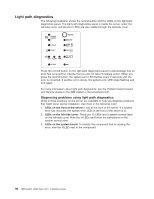
Light path diagnostics LEDs The following table describes the LEDs on the light path diagnostics panel and suggested actions to correct the detected problems. v Follow the suggested actions in the order in which they are listed in the Action column until the problem is solved. v See the Problem Determination and Service Guide on the IBM System x Documentation CD to determine which components are customer replaceable units (CRU) and which components are field replaceable units (FRU). v If an action step is preceded by "(Trained service technician only)," that step must be performed only by a trained service technician. Lit light path diagnostics LED with the system-error or information LED also lit Description Action All LEDs are off (the power LED is lit; the information LED might be lit). No action is necessary. POWER SUPPLY 1 Power supply 1 has failed or has been removed. Note: In a redundant power configuration, the dc power LED on one power supply might be off. 1. Reinstall the power supply 1. 2. Check the individual power-supply LEDs. 3. Reseat the following components: a. Power supply b. (Trained service technician only) Power backplane 4. Replace the components listed in step 3, one at a time, in the order shown, restarting the server each time. 5. If a 240 V ac fault has occurred, remove ac power before restoring dc power. POWER SUPPLY 2 Power supply 2 has failed or has been removed. Note: In a redundant power configuration, the dc power LED on one power supply might be off. 1. Reinstall the power supply 2. 2. Check the individual power-supply LEDs. 3. Reseat the following components: a. Power supply b. (Trained service technician only) Power backplane 4. Replace the components listed in step 3, one at a time, in the order shown, restarting the server each time. 5. If a 240 V ac fault has occurred, remove ac power before restoring dc power. CONFIG Microprocessor configuration error. 1. Mismatched microprocessors, remove and install two microprocessor of the same cache size, type, and clock speed. 2. Check the system error log for information indicating incompatible components. Chapter 5. Solving problems 91
-
 1
1 -
2
-
3
-
4
-
5
-
6
-
7
-
8
-
9
-
10
-
11
-
12
-
13
-
14
-
15
-
16
-
17
-
18
-
19
-
20
-
21
-
22
-
23
-
24
-
25
-
26
-
27
-
28
-
29
-
30
-
31
-
32
-
33
-
34
-
35
-
36
-
37
-
38
-
39
-
40
-
41
-
42
-
43
-
44
-
45
-
46
-
47
-
48
-
49
-
50
-
51
-
52
-
53
-
54
-
55
-
56
-
57
-
58
-
59
-
60
-
61
-
62
-
63
-
64
-
65
-
66
-
67
-
68
-
69
-
70
-
71
-
72
-
73
-
74
-
75
-
76
-
77
-
78
-
79
-
80
-
81
-
82
-
83
-
84
-
85
-
86
-
87
-
88
-
89
-
90
-
91
-
92
-
93
-
94
-
95
-
96
-
97
-
98
-
99
-
 100
100 -
 101
101 -
 102
102 -
 103
103 -
 104
104 -
 105
105 -
 106
106 -
 107
107 -
 108
108 -
 109
109 -
 110
110 -
111
-
112
-
113
-
114
-
115
-
116
-
117
-
118
-
119
-
120
-
121
-
122
-
123
-
124
 |
 |
