IBM x3500 Installation Guide - Page 25
Removing, left-side, cover, Installing, memory, module - specifications
 |
UPC - 883436005760
View all IBM x3500 manuals
Add to My Manuals
Save this manual to your list of manuals |
Page 25 highlights
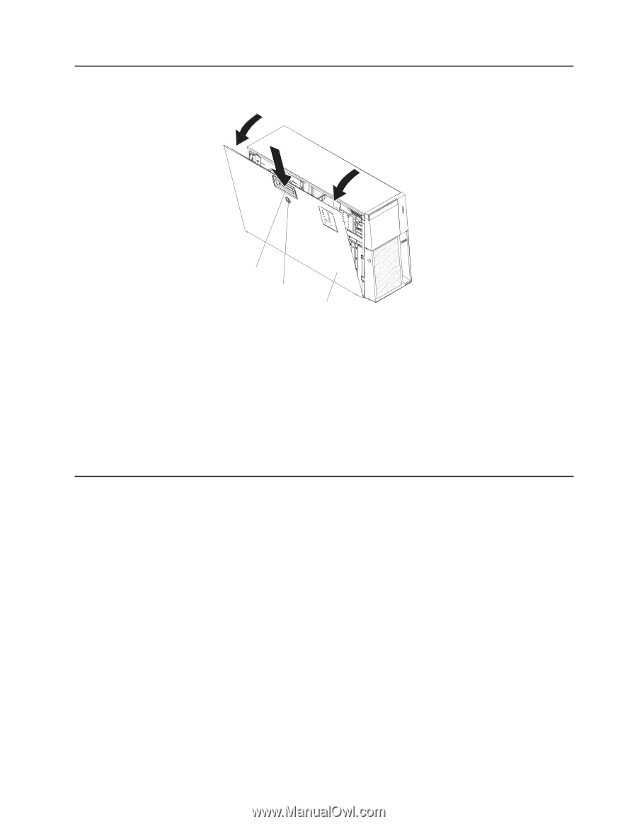
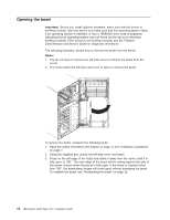
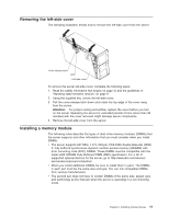
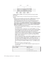
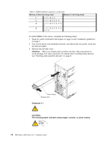
Removing the left-side cover The following illustration shows how to remove the left-side cover from the server. Cover release latch Lock Left-side cover To remove the server left-side cover, complete the following steps: 1. Read the safety information that begins on page vii and the guidelines in "Handling static-sensitive devices" on page 9. 2. Using the supplied key, unlock the left-side cover. 3. Pull the cover-release latch down and rotate the top edge of the cover away from the server. Attention: For proper cooling and airflow, replace the cover before you turn on the server. Operating the server for extended periods of time (more than 30 minutes) with the cover removed might damage server components. 4. Remove the left-side cover from the server. Installing a memory module The following notes describe the types of dual inline memory modules (DIMMs) that the server supports and other information that you must consider when you install DIMMs: v The server supports 667 MHz, 1.8 V, 240-pin, PC2-5300 double-data-rate (DDR) II, fully buffered synchronous dynamic random-access memory (SDRAM) with error correcting code (ECC) DIMMs. These DIMMs must be compatible with the latest 5300 SDRAM Fully Buffered DIMM (FBD) specification. For a list of supported optional devices for the server, go to http://www.ibm.com/servers/ eserver/serverproven/compat/us/. v When you install additional DIMMs, be sure to install them in pairs. The DIMMs in each pair must be the same size and type. You can mix compatible DIMMs from various manufacturers. v The second pair does not have to contain DIMMs of the same size, speed, type, and technology as the first pair when the server is operating in a non-mirroring mode. Chapter 2. Installing optional devices 11
-
 1
1 -
2
-
3
-
4
-
5
-
6
-
7
-
8
-
9
-
10
-
11
-
12
-
13
-
14
-
15
-
16
-
17
-
18
-
19
-
 20
20 -
 21
21 -
 22
22 -
 23
23 -
 24
24 -
 25
25 -
 26
26 -
 27
27 -
 28
28 -
 29
29 -
 30
30 -
31
-
32
-
33
-
34
-
35
-
36
-
37
-
38
-
39
-
40
-
41
-
42
-
43
-
44
-
45
-
46
-
47
-
48
-
49
-
50
-
51
-
52
-
53
-
54
-
55
-
56
-
57
-
58
-
59
-
60
-
61
-
62
-
63
-
64
-
65
-
66
-
67
-
68
-
69
-
70
-
71
-
72
-
73
-
74
-
75
-
76
-
77
-
78
-
79
-
80
-
81
-
82
-
83
-
84
-
85
-
86
-
87
-
88
-
89
-
90
-
91
-
92
-
93
-
94
-
95
-
96
-
97
-
98
-
99
-
100
-
101
-
102
-
103
-
104
-
105
-
106
-
107
-
108
-
109
-
110
-
111
-
112
-
113
-
114
-
115
-
116
-
117
-
118
-
119
-
120
-
121
-
122
-
123
-
124
 |
 |