IBM x3500 Installation Guide - Page 45
Connecting, cables
 |
UPC - 883436005760
View all IBM x3500 manuals
Add to My Manuals
Save this manual to your list of manuals |
Page 45 highlights
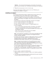
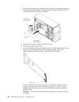
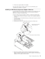
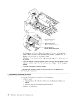
Cover release latch Lock Left-side cover a. Position the left-side cover so that the handle is at the top. b. Place the bottom edge of the cover onto the bottom edge of the server. c. Rotate the top edge of left-side cover toward the server; then, press down on the cover until it clicks into place. d. Using the supplied key, lock the left-side cover and bezel. 3. Connect the cables and power cords. See "Connecting the cables" for more information. Connecting the cables Notes: 1. Turn off the server before you connect any cables to or disconnect any cables from the server or hot-plug adapter. 2. For additional cabling instructions, see the User's Guide on the IBM System x Documentation CD and the documentation that comes with the optional devices. It might be easier for you to route any cables before you install certain optional devices. 3. Cable identifiers are printed on the cables that come with the server and optional devices. Use these identifiers to connect the cables to the correct connectors. The following illustration shows the location of the input and output connectors on the rear of the server. Note: There are two USB connectors on the front of the server. (See "Front view" on page 35 for the location of these two USB connectors.) Chapter 2. Installing optional devices 31
-
 1
1 -
2
-
3
-
4
-
5
-
6
-
7
-
8
-
9
-
10
-
11
-
12
-
13
-
14
-
15
-
16
-
17
-
18
-
19
-
20
-
21
-
22
-
23
-
24
-
25
-
26
-
27
-
28
-
29
-
30
-
31
-
32
-
33
-
34
-
35
-
36
-
37
-
38
-
39
-
 40
40 -
 41
41 -
 42
42 -
 43
43 -
 44
44 -
 45
45 -
 46
46 -
 47
47 -
 48
48 -
 49
49 -
 50
50 -
51
-
52
-
53
-
54
-
55
-
56
-
57
-
58
-
59
-
60
-
61
-
62
-
63
-
64
-
65
-
66
-
67
-
68
-
69
-
70
-
71
-
72
-
73
-
74
-
75
-
76
-
77
-
78
-
79
-
80
-
81
-
82
-
83
-
84
-
85
-
86
-
87
-
88
-
89
-
90
-
91
-
92
-
93
-
94
-
95
-
96
-
97
-
98
-
99
-
100
-
101
-
102
-
103
-
104
-
105
-
106
-
107
-
108
-
109
-
110
-
111
-
112
-
113
-
114
-
115
-
116
-
117
-
118
-
119
-
120
-
121
-
122
-
123
-
124
 |
 |
