Intel BX80605X3430 Data Sheet - Page 21
System Memory Timing Support, System Memory Organization Modes
 |
UPC - 735858210331
View all Intel BX80605X3430 manuals
Add to My Manuals
Save this manual to your list of manuals |
Page 21 highlights
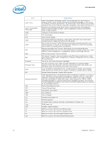
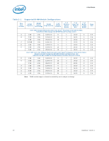
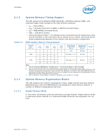
Interfaces 2.1.2 Table 2-2. System Memory Timing Support The IMC supports the following DDR3 Speed Bin, CAS Write Latency (CWL), and command signal mode timings on the main memory interface: • tCL = CAS Latency • tRCD = Activate Command to READ or WRITE Command delay • tRP = PRECHARGE Command Period • CWL = CAS Write Latency • Command Signal modes = 1N indicates a new command may be issued every clock and 2N indicates a new command may be issued every 2 clocks. Command launch mode programming depends on the transfer rate and memory configuration. DDR3 System Memory Timing Support Transfer Rate (MT/s) (ttCCKL ) (ttRCCKD) (ttRCKP) CWL (tCK) Unbuffered DIMM CMD Mode Registered DIMM CMD Mode Notes 1066 1333 6 6 6 5 N/A 1N Only 4 7 7 7 6 See Note 1, 2, 3 1N Only 4 8 8 8 8 8 8 4 9 9 9 7 See Note 1, 2, 3 1N Only 4 10 10 10 4 Note: 1. Two Un-buffered DIMM Memory Configurations = 2N Command Mode at 1067/1333 MHz 2. One Un-buffered DIMM Memory Configurations = 1N Command Mode at 1067/1333 MHz 3. Both Channel A and B will run at same Command Mode based on the slowest mode enabled relative to the memory configurations populated in both channels. For example, if Channel A has both DIMM connectors populated (2N CMD Mode) and Channel B has only one DIMM connector populated (1N CMD Mode) then 2N CMD mode would be enabled for both channels. 4. System Memory timing support is based on availability and is subject to change. 2.1.3 System Memory Organization Modes The IMC supports two memory organization modes, single-channel and dual-channel. Depending upon how the DIMM Modules are populated in each memory channel, a number of different configurations can exist. 2.1.3.1 Single-Channel Mode In this mode, all memory cycles are directed to a single-channel. Single-channel mode is used when either Channel A or Channel B DIMM connectors are populated, but not both. Datasheet, Volume 1 21
-
 1
1 -
2
-
3
-
4
-
5
-
6
-
7
-
8
-
9
-
10
-
11
-
12
-
13
-
14
-
15
-
 16
16 -
 17
17 -
 18
18 -
 19
19 -
 20
20 -
 21
21 -
 22
22 -
 23
23 -
 24
24 -
 25
25 -
 26
26 -
27
-
28
-
29
-
30
-
31
-
32
-
33
-
34
-
35
-
36
-
37
-
38
-
39
-
40
-
41
-
42
-
43
-
44
-
45
-
46
-
47
-
48
-
49
-
50
-
51
-
52
-
53
-
54
-
55
-
56
-
57
-
58
-
59
-
60
-
61
-
62
-
63
-
64
-
65
-
66
-
67
-
68
-
69
-
70
-
71
-
72
-
73
-
74
-
75
-
76
-
77
-
78
-
79
-
80
-
81
-
82
-
83
-
84
-
85
-
86
-
87
-
88
-
89
-
90
-
91
-
92
-
93
-
94
-
95
-
96
-
97
-
98
 |
 |
