Intel BX80605X3430 Data Sheet - Page 23
Rules for Populating Memory Slots
 |
UPC - 735858210331
View all Intel BX80605X3430 manuals
Add to My Manuals
Save this manual to your list of manuals |
Page 23 highlights
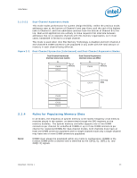
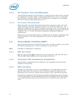
Interfaces 2.1.3.2.2 Dual-Channel Asymmetric Mode This mode trades performance for system design flexibility. Unlike the previous mode, addresses start at the bottom of Channel A and stay there until the end of the highest rank in Channel A, and then addresses continue from the bottom of Channel B to the top. Real world applications are unlikely to make requests that alternate between addresses that sit on opposite channels with this memory organization, so in most cases, bandwidth is limited to a single channel. This mode is used when Intel Flex Memory Technology is disabled and both Channel A and Channel B DIMM connectors are populated in any order with the total amount of memory in each channel being different. Figure 2-2. Dual-Channel Symmetric (Interleaved) and Dual-Channel Asymmetric Modes Dual Channel Interleaved (memory sizes must match) CL CH. B CH. A Top of Memory Dual Channel Asymmetric (memory sizes can differ) CL CH. B Top of Memory CH. A CH.A-top DRB 2.1.4 Note: CH. B CH. A CH. B CH. A 0 0 Rules for Populating Memory Slots In all modes, the frequency of system memory is the lowest frequency of all memory modules placed in the system, as determined through the SPD registers on the memory modules. The system memory controller supports one or two DIMM connectors per channel for unbuffered DIMMs or up to three DIMM connectors per channel for registered DIMMs.For dual-channel modes, both channels must have at least one DIMM connector populated and for single-channel mode only a single-channel may have one or more DIMM connectors populated. DIMM0 must always be populated within any memory configuration. DIMM0 is the furthest DIMM within a channel and is identified by the CS#[1:0], ODT[1:0], and CKE[1:0] signals. Datasheet, Volume 1 23
-
 1
1 -
2
-
3
-
4
-
5
-
6
-
7
-
8
-
9
-
10
-
11
-
12
-
13
-
14
-
15
-
16
-
17
-
 18
18 -
 19
19 -
 20
20 -
 21
21 -
 22
22 -
 23
23 -
 24
24 -
 25
25 -
 26
26 -
 27
27 -
 28
28 -
29
-
30
-
31
-
32
-
33
-
34
-
35
-
36
-
37
-
38
-
39
-
40
-
41
-
42
-
43
-
44
-
45
-
46
-
47
-
48
-
49
-
50
-
51
-
52
-
53
-
54
-
55
-
56
-
57
-
58
-
59
-
60
-
61
-
62
-
63
-
64
-
65
-
66
-
67
-
68
-
69
-
70
-
71
-
72
-
73
-
74
-
75
-
76
-
77
-
78
-
79
-
80
-
81
-
82
-
83
-
84
-
85
-
86
-
87
-
88
-
89
-
90
-
91
-
92
-
93
-
94
-
95
-
96
-
97
-
98
 |
 |
