Intel BX80605X3430 Data Sheet - Page 58
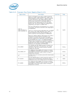
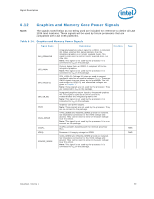
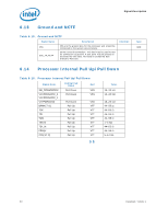
Table 6-13., Processor Core Power Signals Sheet 2 of 2
 |
UPC - 735858210331
View all Intel BX80605X3430 manuals
Add to My Manuals
Save this manual to your list of manuals |
Page 58 highlights
Signal Description Table 6-13. Processor Core Power Signals (Sheet 2 of 2) Signal Name VID[7:6] VID[5:3]/CSC[2:0] VID[2:0]/MSID[2:0] VSS_SENSE VSS_SENSE_VTT VTT VTT_SELECT VTT_SENSE Description VID[7:0] (Voltage ID) are used to support automatic sVeolletacgtieonReogf uploawtoerr-Dsuopwpnly(VvRolDta)g1e1s.1(VDCeC)s.igRneGfeuridtoeltinhees for more information. The voltage supply for these signals must be valid before the VR can supply the processor. Conversely, the VR output must bVeCC to disabled until the voltage supply for the VID signals become valid. The VR must supply the voltage that is requested by the signals, or disable itself. VID7 1 k raensdistVoIrD(6ThshisovualdlubeeistieladtcsheepdaroantetlhyetorisVinSSg using edge a of VTTPWRGOOD). CSC[2:0]-Current Sense Configuration bits, for ISENSE gain setting. See Voltage Regulator-Down (VRD) 11.1 Design Guidelines for gain setting information. This value is latched on the rising edge of VTTPWRGOOD. MSID[2:0] (Market Segment Identification) are used to indicate the maximum platform capability to the processor. A processor will only boot if the MSID[2:0] pins are strapped to the appropriate setting (or higher) on the platform (see Table 7-3 for MSID encodings). MSID is used to help protect the platform by preventing a higher power processor from booting in a platform designed for lower power processors. MSID[2:0] are latched on the rising edge of VTTPWRGOOD. VCC_SENSE and VSS_SENSE provide an isolated, low impedance connection to the processor core voltage and ground. They can be used to sense or measure voltage near the silicon. VTT_SENSE and VSS_SENSE_VTT provide an isolated, low impedance connection to the processor VTT voltage and ground. They can be used to sense or measure voltage near the silicon. Processor power for the memory controller, shared cache and I/O (1.1 V). The VTT_SELECT signal is used to select the correct VTT voltage level for the processor. The processor will be configured to drive a low voltage level for VTT_SELECT. VTT_SENSE and VSS_SENSE_VTT provide an isolated, low impedance connection to the processor VTT voltage and ground. They can be used to sense or measure voltage near the silicon. Direction I/O O Type CMOS Analog Analog PWR CMOS Analog 58 Datasheet, Volume 1
-
 1
1 -
2
-
3
-
4
-
5
-
6
-
7
-
8
-
9
-
10
-
11
-
12
-
13
-
14
-
15
-
16
-
17
-
18
-
19
-
20
-
21
-
22
-
23
-
24
-
25
-
26
-
27
-
28
-
29
-
30
-
31
-
32
-
33
-
34
-
35
-
36
-
37
-
38
-
39
-
40
-
41
-
42
-
43
-
44
-
45
-
46
-
47
-
48
-
49
-
50
-
51
-
52
-
 53
53 -
 54
54 -
 55
55 -
 56
56 -
 57
57 -
 58
58 -
 59
59 -
 60
60 -
 61
61 -
 62
62 -
 63
63 -
64
-
65
-
66
-
67
-
68
-
69
-
70
-
71
-
72
-
73
-
74
-
75
-
76
-
77
-
78
-
79
-
80
-
81
-
82
-
83
-
84
-
85
-
86
-
87
-
88
-
89
-
90
-
91
-
92
-
93
-
94
-
95
-
96
-
97
-
98
 |
 |
