Intel BX80605X3430 Data Sheet - Page 70
DC Specifications
 |
UPC - 735858210331
View all Intel BX80605X3430 manuals
Add to My Manuals
Save this manual to your list of manuals |
Page 70 highlights
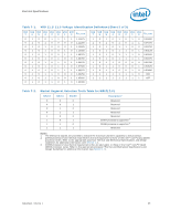
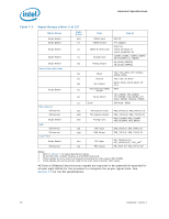
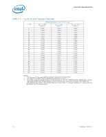
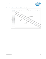
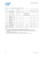
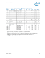
Electrical Specifications 7.9 7.9.1 DC Specifications The processor DC specifications in this section are defined at the processor pads, unless noted otherwise. See Chapter 8 for the processor land listings and Chapter 6 for signal definitions. Voltage and current specifications are detailed in Table 7-5 and Table 7-6. For platform planning, refer to Table 7-7 that provides VCC static and transient tolerances. This same information is presented graphically in Figure 7-1. The DC specifications for the DDR3 signals are listed in Table 7-8 Control Sideband and Test Access Port (TAP) are listed in Table 7-9. Table 7-5 through Table 7-6 list the DC specifications for the processor and are valid only while meeting the thermal specifications (as specified in the processor Thermal and Mechanical Specifications and Guidelines), clock frequency, and input voltages. Care should be taken to read all notes associated with each parameter. Voltage and Current Specifications Table 7-5. Processor Core Active and Idle Mode DC Voltage and Current Specifications Symbol VID VCC VCC,BOOT Parameter VID Range VCC for processor core Default VCC voltage for initial power up Processor Number For Intel Xeon processor 3400 series with 95 W TDP Min Typ Max 0.6500 - 1.4000 See Table 7-7 and Figure 7-1 - 1.10 - Unit V V V Note 1, 2, 3 X3480 ICC X3470 X3460 X3450 X3440 X3430 3.06 GHz 2.93 GHz 2.80 GHz 2.66 GHz 2.53 GHz 2.40 GHz 110 - - 110 A 4 110 110 110 110 Processor For Intel Xeon processor 3400 ICC Number series with 45 W TDP - - A 4 L3426 1.86 GHz 55 Sustained ICC; recommended design target ICC_TDC for Intel Xeon processor 3400 series with 95 W TDP - - 90 A ICC_TDC 2009A target fSour sItnatienleXdeIoCnC;prreoccoemssmore3n4d0e0d design series - - 45 A with 45 W TDP Notes: 1. Each processor is programmed with a maximum valid voltage identification value (VID) that is set at manufacturing and cannot be altered. Individual maximum VID values are calibrated during manufacturing such that two processors at the same frequency may have different settings within the VID range. Note that this differs from the VID employed by the processor during a power management event (Adaptive Thermal Monitor, Enhanced Intel SpeedStep Technology, or Low Power States). 2. The voltage specification requirements are measured across VCC_SENSE and VSS_SENSE lands at the socket with a 100-MHz bandwidth oscilloscope, 1.5 pF maximum probe capacitance, and 1-M minimum impedance. The maximum length of ground wire on the probe should be less than 5 mm. Ensure external noise from the system is not coupled into the oscilloscope probe. 3. Refer to Table 7-7 and Figure 7-1 for the minimum, typical, and maximum VCC allowed for a given current. The processor should not be subjected to any VCC and ICC combination wherein VCC exceeds VCC_MAX for a given current. 4. ICC_MAX specification is based on the VCC_MAX loadline. Refer to Figure 7-1 for details. 70 Datasheet, Volume 1
-
 1
1 -
2
-
3
-
4
-
5
-
6
-
7
-
8
-
9
-
10
-
11
-
12
-
13
-
14
-
15
-
16
-
17
-
18
-
19
-
20
-
21
-
22
-
23
-
24
-
25
-
26
-
27
-
28
-
29
-
30
-
31
-
32
-
33
-
34
-
35
-
36
-
37
-
38
-
39
-
40
-
41
-
42
-
43
-
44
-
45
-
46
-
47
-
48
-
49
-
50
-
51
-
52
-
53
-
54
-
55
-
56
-
57
-
58
-
59
-
60
-
61
-
62
-
63
-
64
-
 65
65 -
 66
66 -
 67
67 -
 68
68 -
 69
69 -
 70
70 -
 71
71 -
 72
72 -
 73
73 -
 74
74 -
 75
75 -
76
-
77
-
78
-
79
-
80
-
81
-
82
-
83
-
84
-
85
-
86
-
87
-
88
-
89
-
90
-
91
-
92
-
93
-
94
-
95
-
96
-
97
-
98
 |
 |