Intel BX80605X3430 Data Sheet - Page 77
Platform Environmental Control Interface PECI, DC Specifications
 |
UPC - 735858210331
View all Intel BX80605X3430 manuals
Add to My Manuals
Save this manual to your list of manuals |
Page 77 highlights
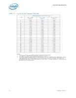
Electrical Specifications 7.10 Platform Environmental Control Interface (PECI) DC Specifications PECI is an Intel proprietary interface that provides a communication channel between Intel processors and chipset components to external thermal monitoring devices. The processor contains a Digital Thermal Sensor (DTS) that reports a relative die temperature as an offset from Thermal Control Circuit (TCC) activation temperature. Temperature sensors located throughout the die are implemented as analog-to-digital converters calibrated at the factory. PECI provides an interface for external devices to read the DTS temperature for thermal management and fan speed control. For the PECI command set supported by the processor, refer to the appropriate processor Thermal and Mechanical Specifications and Design Guidelines for additional information (see Section 1.7). 7.10.1 DC Characteristics The PECI interface operates at a nominal voltage set by VTT. The set of DC electrical specifications shown in Table 7-11 is used with devices normally operating from a VTT interface supply. VTT nominal levels will vary between processor families. All PECI devices will operate at the VTT level determined by the processor installed in the system. For specific nominal VTT levels, refer to Table 7-6. Table 7-11. PECI DC Electrical Limits Symbol Definition and Conditions Min Max Units Notes1 Vin Input Voltage Range -0.150 VTT V Vhysteresis Hysteresis 0.1 * VTT N/A V Vn Negative-Edge Threshold Voltage 0.275 * VTT 0.500 * VTT V Vp Positive-Edge Threshold Voltage 0.550 * VTT 0.725 * VTT V Isource High-Level Output Source (VOH = 0.75 * VTT) -6.0 N/A mA Isink Low-Level Output Sink (VOL = 0.25 * VTT) 0.5 1.0 mA Ileak+ High Impedance State Leakage to VTT (Vleak = VOL) N/A 100 µA 2 Ileak- High Impedance Leakage to GND (Vleak = VOH) N/A 100 µA 2 Cbus Bus Capacitance per Node N/A 10 pF Vnoise Signal Noise Immunity above 300 MHz 0.1 * VTT N/A Vp-p Notes: 1. VTT supplies the PECI interface. PECI behavior does not affect VTT min/max specifications. 2. The leakage specification applies to powered devices on the PECI bus. Datasheet, Volume 1 77
-
 1
1 -
2
-
3
-
4
-
5
-
6
-
7
-
8
-
9
-
10
-
11
-
12
-
13
-
14
-
15
-
16
-
17
-
18
-
19
-
20
-
21
-
22
-
23
-
24
-
25
-
26
-
27
-
28
-
29
-
30
-
31
-
32
-
33
-
34
-
35
-
36
-
37
-
38
-
39
-
40
-
41
-
42
-
43
-
44
-
45
-
46
-
47
-
48
-
49
-
50
-
51
-
52
-
53
-
54
-
55
-
56
-
57
-
58
-
59
-
60
-
61
-
62
-
63
-
64
-
65
-
66
-
67
-
68
-
69
-
70
-
71
-
 72
72 -
 73
73 -
 74
74 -
 75
75 -
 76
76 -
 77
77 -
 78
78 -
 79
79 -
 80
80 -
 81
81 -
 82
82 -
83
-
84
-
85
-
86
-
87
-
88
-
89
-
90
-
91
-
92
-
93
-
94
-
95
-
96
-
97
-
98
 |
 |
