Intel BX80605X3430 Data Sheet - Page 71
Table 7-6., Processor Uncore I/O Buffer Supply DC Voltage and Current Specifications - motherboard
 |
UPC - 735858210331
View all Intel BX80605X3430 manuals
Add to My Manuals
Save this manual to your list of manuals |
Page 71 highlights
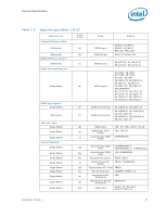
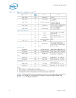
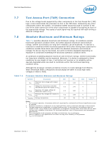
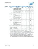
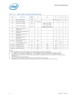
Electrical Specifications Table 7-6. Processor Uncore I/O Buffer Supply DC Voltage and Current Specifications Symbol Parameter Min Typ Max Unit Note Voltage for the memory controller and shared cache defined at the socket motherboard VTT pinfield 1.045 1.10 1.155 V 1 VTT via. Voltage for the memory controller and shared cache defined across 1.023 1.10 1.117 V 2 VTT_SENSE and VSS_SENSE_VTT. VDDQ Processor I/O supply voltage for DDR3 1.425 1.5 1.575 V VCCPLL PLL supply voltage (DC + AC specification) 1.71 1.8 1.89 V Intel Xeon processor 3400 series ITT with 95 W TDP: Current for the memory controller and Shared - - Cache 35 A Intel Xeon processor 3400 series ITT with 45 W TDP: Current for the memory controller and Shared - - Cache 27 A Intel Xeon processor 3400 series ITT_TDC with 95 W TDP: Sustained current for the memory controller and - - Shared Cache 30 A Intel Xeon processor 3400 series ITT_TDC with 45 W TDP: Sustained current for the memory controller and - - Shared Cache 22 A IDDQ Processor I/O supply current for DDR3 - - 6 A IDDQ_TDC Processor I/O supply sustained current for DDR3 - - 6 A IDDQ_STANDBY Processor I/O supply standby current for DDR3 - - 0.650 A ICC_VCCPLL ICC_VCCPLL_TDC PLL supply current PLL sustained supply current - - 1.1 A - - 0.7 A Notes: 1. VTT must be provided using a separate voltage source and not be connected to VCC. The voltage specification requirements are defined in the middle of the VTT pinfield at the processor socket vias on the bottom side of the baseboard. The voltage specifications are measured with a 20-MHz bandwidth oscilloscope, 1.5 pF maximum probe capacitance, and 1 M minimum impedance. The maximum length of ground wire on the probe should be less than 5 mm. Ensure external noise from the system is not coupled into the oscilloscope probe. 2. VTT must be provided using a separate voltage source and not be connected to VCC. The voltage specification requirements are defined across VTT_SENSE and VSS_SENSE_VTT lands at the processor socket vias on the bottom side of the baseboard. The requirements across the SENSE signals account for voltage drops and impedances across the baseboard vias, socket, and processor package up to the processor Si. The voltage specifications are measured with a 20-MHz bandwidth oscilloscope, 1.5 pF maximum probe capacitance, and 1 M minimum impedance. The maximum length of ground wire on the probe should be less than 5 mm. Ensure external noise from the system is not coupled into the oscilloscope probe. Datasheet, Volume 1 71
-
 1
1 -
2
-
3
-
4
-
5
-
6
-
7
-
8
-
9
-
10
-
11
-
12
-
13
-
14
-
15
-
16
-
17
-
18
-
19
-
20
-
21
-
22
-
23
-
24
-
25
-
26
-
27
-
28
-
29
-
30
-
31
-
32
-
33
-
34
-
35
-
36
-
37
-
38
-
39
-
40
-
41
-
42
-
43
-
44
-
45
-
46
-
47
-
48
-
49
-
50
-
51
-
52
-
53
-
54
-
55
-
56
-
57
-
58
-
59
-
60
-
61
-
62
-
63
-
64
-
65
-
 66
66 -
 67
67 -
 68
68 -
 69
69 -
 70
70 -
 71
71 -
 72
72 -
 73
73 -
 74
74 -
 75
75 -
 76
76 -
77
-
78
-
79
-
80
-
81
-
82
-
83
-
84
-
85
-
86
-
87
-
88
-
89
-
90
-
91
-
92
-
93
-
94
-
95
-
96
-
97
-
98
 |
 |
