Intel BX80605X3430 Data Sheet - Page 61
Electrical Specifications
 |
UPC - 735858210331
View all Intel BX80605X3430 manuals
Add to My Manuals
Save this manual to your list of manuals |
Page 61 highlights
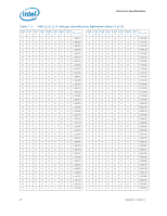
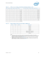
Electrical Specifications 7 Electrical Specifications 7.1 7.2 Caution: 7.2.1 Power and Ground Lands The processor has VCC, VTT, VDDQ, VCCPLL, VAXG, and VSS (ground) inputs for onchip power distribution. All power lands must be connected to their respective processor power planes, while all VSS lands must be connected to the system ground plane. Use of multiple power and ground planes is recommended to reduce I*R drop. The VCC lands must be supplied with the voltage determined by the processor Voltage IDentification (VID) signals. Table 7-1 specifies the voltage level for the various VIDs. Decoupling Guidelines Due to its large number of transistors and high internal clock speeds, the processor is capable of generating large current swings between low- and full-power states. This may cause voltages on power planes to sag below their minimum values, if bulk decoupling is not adequate. Larger bulk storage (CBULK), such as electrolytic capacitors, supply current during longer lasting changes in current demand (for example, coming out of an idle condition). Similarly, capacitors act as a storage well for current when entering an idle condition from a running condition. To keep voltages within specification, output decoupling must be properly designed. Design the board to ensure that the voltage provided to the processor remains within the specifications listed in Table 7-5. Failure to do so can result in timing violations or reduced lifetime of the processor. For further information and design guidelines, refer to the Voltage Regulator Down (VRD) 11.1 Design Guidelines. Voltage Rail Decoupling The voltage regulator solution needs to provide: • bulk capacitance with low effective series resistance (ESR). • a low interconnect resistance from the regulator to the socket. • bulk decoupling to compensate for large current swings generated during poweron, or low-power idle state entry/exit. The power delivery solution must ensure that the voltage and current specifications are met, as defined in Table 7-5. Datasheet, Volume 1 61
-
 1
1 -
2
-
3
-
4
-
5
-
6
-
7
-
8
-
9
-
10
-
11
-
12
-
13
-
14
-
15
-
16
-
17
-
18
-
19
-
20
-
21
-
22
-
23
-
24
-
25
-
26
-
27
-
28
-
29
-
30
-
31
-
32
-
33
-
34
-
35
-
36
-
37
-
38
-
39
-
40
-
41
-
42
-
43
-
44
-
45
-
46
-
47
-
48
-
49
-
50
-
51
-
52
-
53
-
54
-
55
-
 56
56 -
 57
57 -
 58
58 -
 59
59 -
 60
60 -
 61
61 -
 62
62 -
 63
63 -
 64
64 -
 65
65 -
 66
66 -
67
-
68
-
69
-
70
-
71
-
72
-
73
-
74
-
75
-
76
-
77
-
78
-
79
-
80
-
81
-
82
-
83
-
84
-
85
-
86
-
87
-
88
-
89
-
90
-
91
-
92
-
93
-
94
-
95
-
96
-
97
-
98
 |
 |
