JVC DLA-X550R Instruction Manual - Page 67
Command Format, Header, Unit ID, Command and data, Others
 |
View all JVC DLA-X550R manuals
Add to My Manuals
Save this manual to your list of manuals |
Page 67 highlights
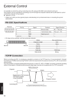
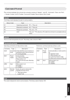
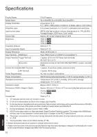
Command Format The command between this unit and the computer consists of "Header", "Unit ID", "Command", "Data" and "End". 0 Header (1 byte), Unit ID (2 bytes), Command (2 bytes), Data (n bytes), End (1 byte) Header This binary code indicates the start of communication. Binary Code 21 3F 40 06 Type Description Operating command PC " This unit Reference command PC " This unit Response command This unit " PC ACK This unit " PC (returns to PC after the command is accepted without error) Unit ID This is a code that specifies the unit. The binary code is fixed at "8901". Command and data Operating command and data (binary code) Command Type Description 0000 Connection Check whether communication is check enabled between this unit and the PC during standby. 5057 Power supply During standby 31: Turns on the power When power is on 30: Turns off the power (Standby mode) 4950 Input When power is on 36: HDMI 1 37: HDMI 2 5243 Remote control Sends the same code as the supplied remote control. 0 "Remote Control Code"P. 68 Reference command and data (binary code) Command Type 5057 Power supply 4950 Input Description During standby or when power is on 30: Standby mode 31: When power is on 32: In the Cool-down mode 34: When error occurs on this unit When power is on 36: HDMI 1 37: HDMI 2 End This code indicates the end of communication. The binary code is fixed at "0A". Others 67
-
 1
1 -
2
-
3
-
4
-
5
-
6
-
7
-
8
-
9
-
10
-
11
-
12
-
13
-
14
-
15
-
16
-
17
-
18
-
19
-
20
-
21
-
22
-
23
-
24
-
25
-
26
-
27
-
28
-
29
-
30
-
31
-
32
-
33
-
34
-
35
-
36
-
37
-
38
-
39
-
40
-
41
-
42
-
43
-
44
-
45
-
46
-
47
-
48
-
49
-
50
-
51
-
52
-
53
-
54
-
55
-
56
-
57
-
58
-
59
-
60
-
61
-
 62
62 -
 63
63 -
 64
64 -
 65
65 -
 66
66 -
 67
67 -
 68
68 -
 69
69 -
 70
70 -
 71
71 -
 72
72 -
73
-
74
-
75
-
76
-
77
-
78
-
79
-
80
 |
 |
