Lantronix XPort XChip - User Guide - Page 36
Configurable Pin Functions, Apply Settings, Apply Defaults
 |
View all Lantronix XPort manuals
Add to My Manuals
Save this manual to your list of manuals |
Page 36 highlights
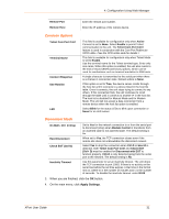
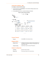
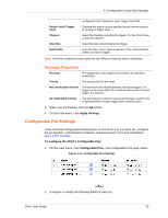
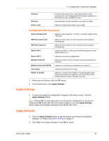
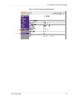
4: Configuration Using Web Manager Function Direction Active Level From the drop-down menu, select the purpose of the specified pin. See Configurable Pin Functions (below) for a description of each available function. Select whether the pin functions as an input or output. Select the signal active level (Low or High). Configurable Pin Functions General Purpose I/O Monitors input using the 77F0 port or controls output by the 77F0 port. HW Flow Control Out Allows for flow control on the connection with hardware handshaking. HW Flow Control In Allows for flow control on the connection with hardware handshaking. Status LED 1 Indicates channel 1 status and extended diagnostics when status LED 3 is lit. Status LED 3 Indicates errors and configurations. Modem Control In Allows for control of the connection (and disconnection) of channel 1. Modem Control Out (DCD) Indicates a connection is established on channel 1. Link Status Indicates the Ethernet link state. RS485 Tx Enable Allows for control of the RS485 Tx Output Enable signal. This function must be mapped to one of the CPs for the RS485 interface mode to operate correctly. 3. When you are finished, click the OK button. 4. On the main menu, click Apply Settings. Apply Settings 1. To save and apply the configuration changes to the device server, click the Apply Settings button. Note: Clicking OK on each page does not change the configuration on the device. Clicking the OK button tells the XPort what changes to use; the Apply Settings button makes the changes permanent and reboots the XPort. Apply Defaults 1. Click the Apply Defaults button to set the device server back to the default settings. For details see Default Settings on page 67. 2. Click Yes to set factory settings or click No to cancel. XPort User Guide 36
-
 1
1 -
2
-
3
-
4
-
5
-
6
-
7
-
8
-
9
-
10
-
11
-
12
-
13
-
14
-
15
-
16
-
17
-
18
-
19
-
20
-
21
-
22
-
23
-
24
-
25
-
26
-
27
-
28
-
29
-
30
-
 31
31 -
 32
32 -
 33
33 -
 34
34 -
 35
35 -
 36
36 -
 37
37 -
 38
38 -
 39
39 -
 40
40 -
 41
41 -
42
-
43
-
44
-
45
-
46
-
47
-
48
-
49
-
50
-
51
-
52
-
53
-
54
-
55
-
56
-
57
-
58
-
59
-
60
-
61
-
62
-
63
-
64
-
65
-
66
-
67
-
68
-
69
-
70
-
71
-
72
-
73
-
74
-
75
-
76
-
77
-
78
-
79
-
80
-
81
-
82
-
83
-
84
-
85
-
86
-
87
 |
 |
