Panasonic D10000U Operating Instructions - Page 20
Adjusting the feet, Projection scheme, Installation geometry - pt projector
 |
UPC - 791871111413
View all Panasonic D10000U manuals
Add to My Manuals
Save this manual to your list of manuals |
Page 20 highlights
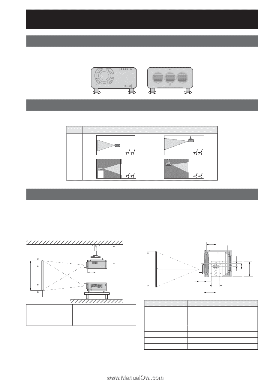
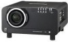
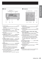
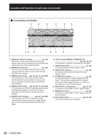
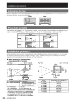
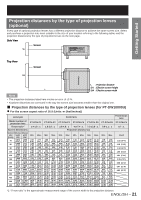
Installation (continued) Adjusting the feet The four adjustable feet mounted at the bottom of the projector are level-adjustable (0 mm-15 mm) which can be used when the floor surface is not horizontal. (Front) (Rear) Projection scheme This projector can use any of the four projection schemes. Select the most suitable scheme to the situation of your location. Use the OPTION menu on the menu screen to choose the desired projection scheme. (p. 76) Floor Ceiling Front Rear Installation geometry When planning the projector and screen geometry, refer to the figures below and the information on the next page for reference. After the projector is roughly positioned, picture size and vertical picture positioning can be finely adjusted with the powered zoom lens and lens shifting mechanism. ● When attaching an optional ceiling mount bracket (ET-PKD100H) Side View (unit : mm/inch) Top View (unit : mm/inch) 200 (7.9˝) SH 580.5 - 700.5 (22.9˝ - 27.6˝) SW 66 120 (2.6˝) (4.7˝) 314 (12.4˝) H L 254 (10˝) L H Screen L: Projection distance SW: Image width SH: Height of the image H: Vertical distance between the lens Center level and the bottom edge of the projected image * For PT-D10000U: H = 0 to SH For PT-DW10000U: H = -0.1 × SH to 1.1 × SH * However, if the ET-D75LE5 has been installed, the value will be fixed at H=SH/2 for both the PT-D10000U and PT-DW10000U. If the ET-D75LE6 has been installed, the values will be H = 0.1 × SH to 0.9 × SH for the PT-D10000U, and H = 0 to SH for the PT-DW10000U. 20 - ENGLISH L Screen Lens ET-D75LE1 ET-D75LE2 ET-D75LE3 ET-D75LE4 ET-D75LE5 ET-D75LE6 ET-D75LE8 L1 254 (10˝) 175 (6.9˝) Dimension of L1 (Approx.) 62.5 (2.5˝) 47 (1.9˝) 50.5 (2˝) 74.4 (2.9˝) 150.5 (5.9˝) 160 (6.3˝) 202.5 (8˝)
-
 1
1 -
2
-
3
-
4
-
5
-
6
-
7
-
8
-
9
-
10
-
11
-
12
-
13
-
14
-
 15
15 -
 16
16 -
 17
17 -
 18
18 -
 19
19 -
 20
20 -
 21
21 -
 22
22 -
 23
23 -
 24
24 -
 25
25 -
26
-
27
-
28
-
29
-
30
-
31
-
32
-
33
-
34
-
35
-
36
-
37
-
38
-
39
-
40
-
41
-
42
-
43
-
44
-
45
-
46
-
47
-
48
-
49
-
50
-
51
-
52
-
53
-
54
-
55
-
56
-
57
-
58
-
59
-
60
-
61
-
62
-
63
-
64
-
65
-
66
-
67
-
68
-
69
-
70
-
71
-
72
-
73
-
74
-
75
-
76
-
77
-
78
-
79
-
80
-
81
-
82
-
83
-
84
-
85
-
86
-
87
-
88
-
89
-
90
-
91
-
92
-
93
-
94
-
95
-
96
-
97
-
98
-
99
-
100
-
101
-
102
-
103
-
104
-
105
-
106
-
107
-
108
-
109
-
110
-
111
-
112
-
113
-
114
-
115
-
116
-
117
-
118
-
119
-
120
-
121
-
122
-
123
-
124
-
125
-
126
-
127
-
128
-
129
-
130
-
131
-
132
 |
 |